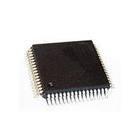
SAK-XC164CM-16F20F BA Infineon Technologies, SAK-XC164CM-16F20F BA Datasheet - Page 52

SAK-XC164CM-16F20F BA
Manufacturer Part Number
SAK-XC164CM-16F20F BA
Description
IC MCU 16BIT FLASH 64-LQFP
Manufacturer
Infineon Technologies
Series
XC16xr
Datasheet
1.SAF-XC164CM-4F20F_AA.pdf
(70 pages)
Specifications of SAK-XC164CM-16F20F BA
Program Memory Type
FLASH
Program Memory Size
128KB (128K x 8)
Package / Case
64-LFQFP
Core Processor
C166SV2
Core Size
16-Bit
Speed
20MHz
Connectivity
CAN, SPI, UART/USART
Peripherals
PWM, WDT
Number Of I /o
47
Ram Size
8K x 8
Voltage - Supply (vcc/vdd)
2.35 V ~ 2.7 V
Data Converters
A/D 14x8/10b
Oscillator Type
Internal
Operating Temperature
-40°C ~ 125°C
Processor Series
XC164x
Core
C166S V2
Data Bus Width
16 bit
Data Ram Size
8 KB
Interface Type
ASC/CAN/SSC
Maximum Clock Frequency
20 MHz
Number Of Programmable I/os
47
Number Of Timers
5
Operating Supply Voltage
5 V
Maximum Operating Temperature
+ 125 C
Mounting Style
SMD/SMT
3rd Party Development Tools
PK166, CA166, AR166, ULINK2
Minimum Operating Temperature
- 40 C
On-chip Adc
14-ch x 10-bit
Packages
PG-LQFP-64
Max Clock Frequency
20.0 MHz
Sram (incl. Cache)
8.0 KByte
Can Nodes
2
A / D Input Lines (incl. Fadc)
14
Program Memory
128.0 KByte
Lead Free Status / RoHS Status
Lead free / RoHS Compliant
For Use With
B158-H8961-X-X-7600IN - KIT EASY XC164CMXC164CMUCANIN - KIT U-CAN STARTER XC164CM
Eeprom Size
-
Lead Free Status / Rohs Status
Lead free / RoHS Compliant
Other names
SP000245661
5) Overload conditions occur if the standard operating conditions are exceeded, i.e. the voltage on any pin
6) Not subject to production test - verified by design/characterization.
7) An overload current (
8) The timing is valid for pin drivers operating in default current mode (selected after reset). Reducing the output
Parameter Interpretation
The parameters listed in the following partly represent the characteristics of the
XC164CM and partly its demands on the system. To aid in interpreting the parameters
right, when evaluating them for a design, they are marked in column “Symbol”:
CC (Controller Characteristics):
The logic of the XC164CM will provide signals with the respective characteristics.
SR (System Requirement):
The external system must provide signals with the respective characteristics to the
XC164CM.
Data Sheet
exceeds the specified range:
input overload currents on all pins may not exceed 50 mA. The supply voltages must remain within the
specified limits.
Proper operation is not guaranteed if overload conditions occur on functional pins such as XTAL1.
current adds to the respective pin’s leakage current (
current and is defined by the overload coupling factor
compared to the polarity of the overload current that produces it.
The total current through a pin is |
voltage on analog inputs.
current may lead to increased delays or reduced driving capability (
I
OV
) through a pin injects a certain error current (
V
OV
I
>
TOT
V
DDP
| = |
+ 0.5 V (
I
OZ
| + (|
I
OV
I
OV
50
I
| ×
OZ
> 0) or
K
). The amount of error current depends on the overload
K
OV
OV
. The polarity of the injected error current is inverse
). The additional error current may distort the input
V
OV
<
V
C
SS
L
).
I
- 0.5 V (
INJ
) into the adjacent pins. This error
Electrical Parameters
I
OV
< 0). The absolute sum of
Derivatives
V1.4, 2007-03
XC164CM


