PIC16C745/JW Microchip Technology, PIC16C745/JW Datasheet - Page 25
PIC16C745/JW
Manufacturer Part Number
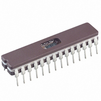
PIC16C745/JW
Description
IC MCU EPROM8KX14 USB A/D 28CDIP
Manufacturer
Microchip Technology
Series
PIC® 16Cr
Datasheets
1.PIC16F616T-ISL.pdf
(8 pages)
2.PIC16C745-ISP.pdf
(165 pages)
3.PIC16C745-ISP.pdf
(6 pages)
4.PIC16C745-ISP.pdf
(6 pages)
Specifications of PIC16C745/JW
Core Processor
PIC
Core Size
8-Bit
Speed
24MHz
Connectivity
SCI, UART/USART, USB
Peripherals
Brown-out Detect/Reset, POR, PWM, WDT
Number Of I /o
22
Program Memory Size
14KB (8K x 14)
Program Memory Type
EPROM, UV
Ram Size
256 x 8
Voltage - Supply (vcc/vdd)
4.35 V ~ 5.25 V
Data Converters
A/D 5x8b
Oscillator Type
External
Operating Temperature
0°C ~ 70°C
Package / Case
28-CDIP (0.300", 7.62mm) Window
Lead Free Status / RoHS Status
Contains lead / RoHS non-compliant
Eeprom Size
-
Available stocks
Company
Part Number
Manufacturer
Quantity
Price
Company:

Part Number:
PIC16C745/JW
Manufacturer:
MICROCHIP
Quantity:
51
Part Number:
PIC16C745/JW
Manufacturer:
MICROCHIP/微芯
Quantity:
20 000


4.2.2.4
This register contains the individual enable bits for the
peripheral interrupts.
REGISTER 4-4: PERIPHERAL INTERRUPT ENABLE1 REGISTER (PIE1: 8Ch)
2000 Microchip Technology Inc.
bit7
bit 7:
bit 6:
bit 5:
bit 4:
bit 3:
bit 2:
bit 1:
bit 0:
Note 1: Parallel slave ports not implemented on the PIC16C745; always maintain this bit clear.
PSPIE
R/W-0
(1)
PIE1 REGISTER
PSPIE
1 = Enables the PSP read/write interrupt
0 = Disables the PSP read/write interrupt
ADIE: A/D Converter Interrupt Enable bit
1 = Enables the A/D interrupt
0 = Disables the A/D interrupt
RCIE: USART Receive Interrupt Enable bit
1 = Enables the USART receive interrupt
0 = Disables the USART receive interrupt
TXIE: USART Transmit Interrupt Enable bit
1 = Enables the USART transmit interrupt
0 = Disables the USART transmit interrupt
USBIE: Universal Serial Bus Interrupt Enable bit
1 = Enables the USB interrupt
0 = Disables the USB interrupt
CCP1IE: CCP1 Interrupt Enable bit
1 = Enables the CCP1 interrupt
0 = Disables the CCP1 interrupt
TMR2IE: TMR2 to PR2 Match Interrupt Enable bit
1 = Enables the TMR2 to PR2 match interrupt
0 = Disables the TMR2 to PR2 match interrupt
TMR1IE: TMR1 Overflow Interrupt Enable bit
1 = Enables the TMR1 overflow interrupt
0 = Disables the TMR1 overflow interrupt
R/W-0
ADIE
(1)
: Parallel Slave Port Read/Write Interrupt Enable bit
R/W-0
RCIE
R/W-0
TXIE
USBIE
R/W-0
Preliminary
CCP1IE
R/W-0
TMR2IE TMR1IE
R/W-0
Note:
Bit PEIE (INTCON<6>) must be set to
enable any peripheral interrupt.
R/W-0
PIC16C745/765
bit0
R = Readable bit
W = Writable bit
U = Unimplemented bit,
-n = Value at POR reset
read as ‘0’
DS41124C-page 25
Related parts for PIC16C745/JW
Image
Part Number
Description
Manufacturer
Datasheet
Request
R

Part Number:
Description:
MICRO CTRL 4K 4MHZ OTP 44PLCC
Manufacturer:
Microchip Technology
Datasheet:
Part Number:
Description:
MICRO CTRL 4K 20MHZ OTP 44PLCC
Manufacturer:
Microchip Technology
Datasheet:

Part Number:
Description:
MICRO CTRL 4K 20MHZ OTP 40DIP
Manufacturer:
Microchip Technology
Datasheet:
Part Number:
Description:
MICRO CTRL 4K 10MHZ OTP ET 40DIP
Manufacturer:
Microchip Technology
Datasheet:
Part Number:
Description:
MICRO CTRL 4K 10MHZ OTP 40DIP
Manufacturer:
Microchip Technology
Datasheet:
Part Number:
Description:
MICRO CTRL 4K 4MHZ OTP 40DIP
Manufacturer:
Microchip Technology
Datasheet:
Part Number:
Description:
MICRO CTRL 4K 4MHZ OTP 40DIP
Manufacturer:
Microchip Technology
Datasheet:

Part Number:
Description:
MICRO CTRL 4K 20MHZ EPROM 40CDIP
Manufacturer:
Microchip Technology
Datasheet:

Part Number:
Description:
8-Bit CMOS Microcontrollers with A/D Converter
Manufacturer:
Microchip Technology
Part Number:
Description:
8-Bit CMOS Microcontrollers with A/D Converter
Manufacturer:
Microchip Technology
Part Number:
Description:
8-Bit CMOS Microcontrollers with A/D Converter
Manufacturer:
Microchip Technology
Part Number:
Description:
8-Bit CMOS Microcontrollers with A/D Converter
Manufacturer:
Microchip Technology
Part Number:
Description:
8-Bit CMOS Microcontrollers with A/D Converter
Manufacturer:
Microchip Technology
Part Number:
Description:
8-Bit CMOS Microcontrollers with A/D Converter
Manufacturer:
Microchip Technology
Part Number:
Description:
8-Bit CMOS Microcontrollers with A/D Converter
Manufacturer:
Microchip Technology