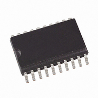
ATAM893T-TKQ Atmel, ATAM893T-TKQ Datasheet - Page 68

ATAM893T-TKQ
Manufacturer Part Number
ATAM893T-TKQ
Description
IC MON TIRE-PRESS ATARX9X SER
Manufacturer
Atmel
Series
MARC4r
Datasheet
1.ATAM893T-TKS.pdf
(98 pages)
Specifications of ATAM893T-TKQ
Core Processor
MARC4
Core Size
4-Bit
Speed
4MHz
Connectivity
SSI (2-Wire, 3 Wire)
Peripherals
Brown-out Detect/Reset, POR, PWM, WDT
Number Of I /o
16
Program Memory Size
4KB (4K x 8)
Program Memory Type
EEPROM
Eeprom Size
64 x 16
Ram Size
256 x 4
Voltage - Supply (vcc/vdd)
1.8 V ~ 6.5 V
Oscillator Type
Internal
Operating Temperature
-40°C ~ 125°C
Package / Case
20-SOIC (5.3mm Width), 20-SO, 20-SOEIAJ
Lead Free Status / RoHS Status
Contains lead / RoHS non-compliant
Data Converters
-
5.3.4.9
5.3.4.10
68
ATAM893-D
Modulation and Demodulation
Internal 2-wire Multi-chip Link
If the shift register is used together with Timer 2 or Timer 3 for modulation or demodulation pur-
poses, the 8-bit synchronous mode must be used. In this case, the unused Port 4 pins can be
used as conventional bi-directional ports.
The modulation and demodulation stages, if enabled, operate as soon as the SSI is activated
(SIR = 0) and cease when deactivated (SIR = 1).
Due to the byte-orientated data control, the SSI (when running normally) generates serial bit
streams which are submultiples of 8 bits. An SSI output masking (OMSK) function permits, how-
ever, the generation of bit streams of any length. The OMSK signal is derived indirectly from the
4-bit prescaler of the Timer 2 and masks out a programmable number of unrequited trailing data
bits during the shifting out of the final data word in the bit stream. The number of non-masked
data bits is defined by the value pre-programmed in the prescaler compare register. To use out-
put masking, the modulator stop mode bit (MSM) must be set to’0’ before programming the final
data word into the SSI transmit buffer. This in turn, enables shift clocks to the prescaler when
this final word is shifted out. On reaching the compare value, the prescaler triggers the OMSK
signal and all following data bits are blanked.
Two additional on-chip pads (MCL_SC and MCL_SD) for the SC and the SD line can be used as
chip-to-chip link for multi-chip applications. These pads can be activated by setting the MCL bit
in the SISC register. They are also used as interface to the internal data EEPROM
Figure 5-46. Multi-chip Link
Figure 5-47. SSI Output Masking Function
T1OUT
SYSCL
TOG2
POUT
SCL
/2
SC
CL2/1
BP40/SC
BP10
V
Shift_CL
DD
4-bit counter 2/1
MCL_SC
SO
Compare 2/1
Microcontroller
SCL
CM1
MSB
U505M
Timer 2
SSI-control
8-bit shift register
SDA
MCL_SD
Multi-chip link
V
BP43/SD
BP13
SS
LSB
Control
OMSK
SI
4680C–4BMCU–01/05
Output
SO


