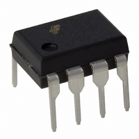
ACE1501EN Fairchild Semiconductor, ACE1501EN Datasheet - Page 17

ACE1501EN
Manufacturer Part Number
ACE1501EN
Description
IC MCU 1KBIT EEPROM 8DIP
Manufacturer
Fairchild Semiconductor
Series
ACEX® 15xxr
Datasheet
1.ACE1501EN.pdf
(33 pages)
Specifications of ACE1501EN
Core Processor
ACE1502
Core Size
8-Bit
Speed
25MHz
Peripherals
Brown-out Detect/Reset, LVD, POR, PWM, WDT
Number Of I /o
6
Program Memory Size
1KB (1K x 8)
Program Memory Type
EEPROM
Eeprom Size
64 x 8
Ram Size
64 x 8
Voltage - Supply (vcc/vdd)
1.8 V ~ 3.6 V
Oscillator Type
Internal
Operating Temperature
-40°C ~ 85°C
Package / Case
8-DIP (0.300", 7.62mm)
Lead Free Status / RoHS Status
Lead free / RoHS Compliant
Data Converters
-
Connectivity
-
ACE1501 Product Family Rev. 1.1
6. As soon as the input capture mode is enabled, the timer
Figure 17. Input Capture Mode
4.5 Mode 4: Difference Input Capture Mode
The Difference Input Capture mode works similarly to the stan-
dard Input Capture mode. However, for the Difference Input
Capture the timer automatically captures the elapsed time
between the selected edges without the core needing to per-
form the calculation.
For example, the standard Input Capture mode requires that the
timer be configured to capture a particular edge (rising or fall-
ing) at which time the timer’s value is copied into the capture
register. If the elapsed time is required, software must move the
captured data into RAM and reconfigure the Input Capture
mode to capture on the next edge (rising or falling). Software
must then subtract the difference between the two edges to
yield useful information.
The Difference Capture mode eliminates the need for software
intervention and allows for capturing very short pulse or cycle
widths. It can be configured to capture the elapsed time
between:
1. rising edge to falling edge
2. rising edge to rising edge
3. falling edge to rising edge
4. falling edge to falling edge
Once configured, the Difference Capture timer waits for the first
selected edge. When the edge transition has occurred, the 16-
bit timer starts counting up based every instruction clock cycle.
It will continue to count until the second selected edge transition
occurs at which time the timer stops and stores the elapse time
into the T1RA register.
Software can now read the difference between transitions
directly without using any processor resources. However, like
Figure 19. Timer 0 Control Register Definition (T0CNTRL)
WKINTEN
(See Table 11 and Table 12)
- LD T1CNTRL, #64H
starts counting. When the selected edge is sensed on T1,
the T1RA register is loaded and a Timer 1 interrupt is
triggered.
Underflow
Interrupt
T1
Bit 7
Interrupt
Capture
Edge Selector
Logic
Bit 6
x
Instruction
Clock
16-bit Timer (TMR1)
; T1C1 is the edge select bit
16-bit Input Capture
Register (T1RA)
Bit 5
x
Data
Bit 4
Bus
x
17
the standard Input Capture mode both the capture (T1PND) and
the underflow (T1C0) flags must be monitored and handled
appropriately. This feature allows the ACEx microcontroller to
capture very small pulses where standard microcontrollers
might have missed cycles due to the limited bandwidth.
Figure 18. Difference Capture Mode
5. Timer 0
Timer 0 is a 12-bit free running idle timer. Upon power-up or any
reset, the timer is reset to 0x000 and then counts up continu-
ously based on the instruction clock of 1MHz (1 µs). Software
cannot read from or write to this timer. However, software can
monitor the timer's pending (T0PND) bit that is set every 8192
cycles (initially 4096 cycles after a reset). The T0PND flag is set
every other time the timer overflows (transitions from 0xFFF to
0x000) through a divide-by-2 circuit. After an overflow, the timer
will reset and restart its counting sequence.
Software can either poll the T0PND bit or vector to an interrupt
subroutine. In order to interrupt on a T0PND, software must be
sure to enable the Timer 0 interrupt enable (T0INTEN) bit in the
Timer 0 control (T0CNTRL) register and also make sure the G
bit is set in SR. Once the timer interrupt is serviced, software
should reset the T0PND bit before exiting the routine. Timer 0
supports the following functions:
1. Exiting from IDLE mode (See Section 16 for details.)
2. Start up delay from HALT mode
3. Watchdog pre-scalar (See Section 6 for details.)
The T0INTEN bit is a read/write bit. If set to 0, interrupt requests
from the Timer 0 are ignored. If set to 1, interrupt requests are
accepted. Upon reset, the T0INTEN bit is reset to 0.
The T0PND bit is a read/write bit. If set to 1, it indicates that a
Timer 0 interrupt is pending. This bit is set by a Timer 0 overflow
and is reset by software or system reset.
The WKINTEN bit is used in the Multi-input Wakeup/Interrupt
block. See Section 8 for details.
Underflow
Bit 3
Interrupt
Interrupt
Capture
T1
x
Edge Selector
Logic
Bit 2
x
Instruction
Clock
16-bit Timer (TMR1)
16-bit Input Capture
Register (T1RA)
T0PND
Bit 1
Difference
Logic
www.fairchildsemi.com
T0INTEN
Bit 0
Data
Bus


