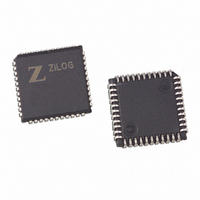
Z8F1601VN020SC Zilog, Z8F1601VN020SC Datasheet - Page 4

Z8F1601VN020SC
Manufacturer Part Number
Z8F1601VN020SC
Description
IC ENCORE MCU FLASH 16K 44-PLCC
Manufacturer
Zilog
Series
Encore!®r
Specifications of Z8F1601VN020SC
Core Processor
Z8
Core Size
8-Bit
Speed
20MHz
Connectivity
I²C, IrDA, SPI, UART/USART
Peripherals
Brown-out Detect/Reset, DMA, POR, PWM, WDT
Number Of I /o
31
Program Memory Size
16KB (16K x 8)
Program Memory Type
FLASH
Ram Size
2K x 8
Voltage - Supply (vcc/vdd)
3 V ~ 3.6 V
Data Converters
A/D 8x10b
Oscillator Type
Internal
Operating Temperature
0°C ~ 70°C
Package / Case
44-LCC (J-Lead)
Lead Free Status / RoHS Status
Contains lead / RoHS non-compliant
Eeprom Size
-
Other names
269-3129
Available stocks
Company
Part Number
Manufacturer
Quantity
Price
Table 1. Z8F640x, Z8F480x, Z8F320x, Z8F240x, Z8F160x Errata for Devices with Date
UP004207-0308
Sl
No
9
10
11
12
Summary
SPI operating as a
Slave in a multi-
Slave system can
lose transmit data.
ADC output is
inaccurate for input
values below
approximately
20 mV.
eZ8 CPU opcode
timing is incorrect for
three Load
instructions.
GPIO Port pins draw
current when input
voltage exceeds one
diode drop above
the supply voltage.
Codes 0239 and Later (Continued)
Errata to Z8F640x, Z8F480x, Z8F320x, Z8F240x, Z8F160x (Z8 Encore!
Description
If the SPI devices on the Z8 Encore!
multi-Slave system, the SPI data can be corrupted by transfers to and from the
Master to other Slaves sharing the same SPI pins. Even though the SS input
pin is High (that is, not selecting the Z8 Encore!'s SPI device), the data will be
shifted into the SPI’s receive buffer. This can overwrite any data that has been
placed in the SPI's transmit buffer by the eZ8 CPU in preparation for transmit
out from the SPI Slave.
Workaround
If it is desired to use the SPI device as a Slave in multi-Slave systems, the
SCK input signal to the Z8 Encore! should be disabled externally when the SS
signal is High. This will prevent shifting in of data by the SPI Slave receiver
when not selected.
The output from the ADC can vary widely when the input signal drops below
about 20 mV.
Workaround
Measure analog inputs only above 20 mV.
The following instructions have timing errors in which an extra (unused) clock
cycle is inserted during instruction execution:
Instruction
Workaround
None. This issue is not likely to affect the user code. If the user code has soft-
ware timing loops, it is possible that future Z8 Encore! products will have dif-
ferent loop timing using the same code. Due the pipelined nature of the eZ8
CPU, timing loops are less likely to be employed than on older Z8
For the 5 V-input tolerant GPIO pins, when the input voltage exceeds
approximately 4.0 V (for a 3.3 V supply voltage), current will be drawn by the
input pin.
Workaround
For GPIO pins that toggle at low frequencies, a 10 kΩ resistor can be placed
between the GPIO pin and the external driver. This will limit the current into the
pin to about 150 µA. For higher frequencies, a 1 kΩ resistor should be used.
This will limit the input current to the pin to about 1.5 mA.
LD
LD
LD
Opcode
E4
E7
E5
Spec Cycles
2
3
3
®
is configured as a Slave device in a
Actual Cycles
3
4
4
®
Page 4 of 15
products.
®
)


