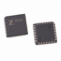
Z8F1601VN020SC Zilog, Z8F1601VN020SC Datasheet - Page 9

Z8F1601VN020SC
Manufacturer Part Number
Z8F1601VN020SC
Description
IC ENCORE MCU FLASH 16K 44-PLCC
Manufacturer
Zilog
Series
Encore!®r
Specifications of Z8F1601VN020SC
Core Processor
Z8
Core Size
8-Bit
Speed
20MHz
Connectivity
I²C, IrDA, SPI, UART/USART
Peripherals
Brown-out Detect/Reset, DMA, POR, PWM, WDT
Number Of I /o
31
Program Memory Size
16KB (16K x 8)
Program Memory Type
FLASH
Ram Size
2K x 8
Voltage - Supply (vcc/vdd)
3 V ~ 3.6 V
Data Converters
A/D 8x10b
Oscillator Type
Internal
Operating Temperature
0°C ~ 70°C
Package / Case
44-LCC (J-Lead)
Lead Free Status / RoHS Status
Contains lead / RoHS non-compliant
Eeprom Size
-
Other names
269-3129
Available stocks
Company
Part Number
Manufacturer
Quantity
Price
Table 2. Z8F640x, Z8F480x, Z8F320x, Z8F240x, Z8F160x Errata for Devices with Date
UP004207-0308
Sl
No
6
7
8
9
Summary
Reset is not gener-
ated when power
supply voltage
(VCC) drops below
the VBO threshold.
The TXST bit in the
SPISTAT register
does not assert until
the transmission
actually starts.
Reading the UART
Status 1 register
through the On-Chip
Debugger always
returns the value
00H.
When used as
simple timers, the
Baud Rate
Generators in the
UARTs, I
generate a
spurious interrupt at
the beginning of the
count.
Codes 0239 and Later (Continued)
2
C, and SPI
Errata to Z8F640x, Z8F480x, Z8F320x, Z8F240x, Z8F160x (Z8 Encore!
Description
Reset is not generated when power supply voltage (VCC) drops below the
VBO threshold.
Workaround
An external VBO circuit is used in the user application to drive the external
RESET pin on the Z8 Encore! when the system supply voltage drops below
acceptable operating levels.
When data is written to the SPIDATA register to be transmitted, the TXST bit in
the SPISTAT register does not assert until the transmission actually starts
which results in a short delay (delay is dependent on the baud rate). It is
possible for software to poll the TXST bit and see a 0 before the transmission
has started. Software may erroneously conclude that the data has already
been transmitted.
Workaround
User code can poll the IRQ bit in the SPISTAT register. Even when the SPI
interrupt is disabled, the IRQ bit will assert at the end of the data transaction
and remain asserted until cleared by software.
The UART Status 1 register is cleared when read. When the OCD reads the
register it holds the read for multiple system clock cycles, thereby clearing the
value before completing the read. Thus, the value returned through the OCD
is always 00H. This issue only affects OCD operation and does not affect
normal operation.
Workaround
Issue a CPU command through the OCD to transfer the UART Status 1
register data to a Register File location. Then the desired UART Status 1
register data can be read from the Register File.
When the Baud Rate Counters for UARTs, I
mode they immediately generate an interrupt. This is because the counters
are incorrectly reset to 0001H rather than the reload value. Since 0001H is the
reload state, it initiates an interrupt request.
Workaround
•
•
•
•
Use one of the four other Timers rather than the Baud Rate Generators in
TIMER mode.
Delay enabling the interrupt for these counters until the count value has
progressed beyond 0001H.
Write the ISR so that is disregards the first interrupt.
Clear the associated interrupt request in the Interrupt Control shortly after
starting the timer.
2
C and SPI are placed in timer
Page 9 of 15
®
)


