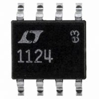
LT1124CS8#PBF Linear Technology, LT1124CS8#PBF Datasheet - Page 5

LT1124CS8#PBF
Manufacturer Part Number
LT1124CS8#PBF
Description
IC OP-AMP LOW NOISE DUAL 8-SOIC
Manufacturer
Linear Technology
Datasheet
1.LT1124CN8PBF.pdf
(18 pages)
Specifications of LT1124CS8#PBF
Amplifier Type
General Purpose
Number Of Circuits
2
Slew Rate
4.5 V/µs
Gain Bandwidth Product
12.5MHz
Current - Input Bias
8nA
Voltage - Input Offset
25µV
Current - Supply
2.3mA
Voltage - Supply, Single/dual (±)
±4 V ~ 18 V
Operating Temperature
0°C ~ 70°C
Mounting Type
Surface Mount
Package / Case
8-SOIC (3.9mm Width)
Lead Free Status / RoHS Status
Lead free / RoHS Compliant
Output Type
-
Current - Output / Channel
-
-3db Bandwidth
-
Available stocks
Company
Part Number
Manufacturer
Quantity
Price
temperature range, V
ELECTRICAL CHARACTERISTICS
The
SYMBOL PARAMETER
V
ΔTemp
I
I
V
CMRR
PSRR
A
V
SR
I
SYMBOL PARAMETER
V
ΔTemp
I
I
V
CMRR
PSRR
A
V
SR
I
OS
B
S
OS
B
S
ΔV
ΔV
OS
CM
VOL
OUT
OS
CM
VOL
OUT
OS
OS
l
denotes the specifi cations which apply over the –40°C ≤ T
Input Offset Voltage
Average Input Offset
Voltage Drift
Input Offset Current
Input Bias Current
Input Voltage Range
Common Mode Rejection Ratio
Power Supply Rejection Ratio
Large-Signal Voltage Gain
Maximum Output Voltage Swing
Slew Rate
Supply Current per Amplifi er
Input Offset Voltage
Average Input Offset
Voltage Drift
Input Offset Current
Input Bias Current
Input Voltage Range
Common Mode Rejection Ratio
Power Supply Rejection Ratio
Large-Signal Voltage Gain
Maximum Output Voltage Swing
Slew Rate
Supply Current per Amplifi er
S
= ±15V, unless otherwise noted.
CONDITIONS (Note 2)
LT1124
LT1125
(Note 5)
LT1124
LT1125
V
V
R
R
R
R
CONDITIONS (Note 2)
LT1124
LT1125
(Note 5)
LT1124
LT1125
V
V
R
R
R
R
CM
S
L
L
L
L
CM
S
L
L
L
L
= ±4V to ±18V
≥ 10k, V
≥ 2k, V
≥ 2k
≥ 2k (Notes 3, 7)
= ±4V to ±18V
≥ 10k, V
≥ 2k, V
≥ 2k
≥ 2k (Notes 3, 7)
= ±11.5V
= ±11.4V
OUT
OUT
OUT
OUT
The
= ±10V
= ±10V
= ±10V
= ±10V
A
l
≤ 85°C temperature range, V
denotes the specifi cations which apply over the 0°C ≤ T
l
l
l
l
l
l
l
l
l
l
l
l
l
l
l
l
l
l
l
l
l
l
l
l
l
l
l
l
±11.5 ±12.4
±12.5 ±13.7
±11.4 ±12.2
±12.5 ±13.6
MIN
MIN
109
112
107
111
4.0
1.5
2.6
3.5
1.2
2.4
LT1124AC/AI
LT1124AC
LT1125AC
LT1125AC
S
TYP
125
125
TYP
±15
124
124
0.3
3.5
2.4
0.3
3.2
3.9
2.4
35
40
±8
15
= ±15V, unless otherwise noted. (Note 10)
40
45
15
15
12
6
7
4
MAX
MAX
3.25
120
140
±35
140
160
±50
25
35
40
50
LT1124/LT1125
1
3
1
±11.5 ±12.4
±11.4 ±12.2
MIN
MIN
102
107
±12
101
106
±12
2.5
1.0
2.4
2.2
0.8
2.1
LT1124C/I
LT1124C
LT1125C
LT1125C
±13.7
±13.6
TYP
122
122
TYP
±17
121
121
0.4
2.5
2.4
0.4
2.3
3.9
2.4
45
50
±9
14
50
55
17
17
12
7
8
4
A
≤ 70°C
MAX
MAX
3.25
170
210
±45
200
240
±65
1.5
1.5
35
45
55
65
3
UNITS
UNITS
11245fe
μV/°C
μV/°C
5
V/μV
V/μV
V/μV
V/μV
V/μs
V/μs
mA
mA
μV
μV
nA
nA
nA
dB
dB
μV
μV
nA
nA
nA
dB
dB
V
V
V
V


