SSM2018PZ Analog Devices Inc, SSM2018PZ Datasheet - Page 3
SSM2018PZ
Manufacturer Part Number
SSM2018PZ
Description
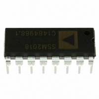
IC AMP AUDIO MONO CLASS AB 16DIP
Manufacturer
Analog Devices Inc
Datasheet
1.SSM2018PZ.pdf
(16 pages)
Specifications of SSM2018PZ
Amplifier Type
Audio
Number Of Circuits
1
Slew Rate
5 V/µs
Gain Bandwidth Product
14MHz
Current - Input Bias
250nA
Voltage - Input Offset
1000µV
Current - Supply
11mA
Voltage - Supply, Single/dual (±)
10 V ~ 36 V, ±5 V ~ 18 V
Operating Temperature
-40°C ~ 85°C
Mounting Type
Through Hole
Package / Case
16-DIP (0.300", 7.62mm)
Amplifier Class
AB
No. Of Channels
1
Supply Voltage Range
± 5V To ± 18V
Load Impedance
100kohm
Operating Temperature Range
-40°C To +85°C
Amplifier Case Style
DIP
No. Of Pins
16
Rohs Compliant
Yes
Lead Free Status / RoHS Status
Lead free / RoHS Compliant
Output Type
-
Current - Output / Channel
-
-3db Bandwidth
-
Lead Free Status / Rohs Status
RoHS Compliant part
Electrostatic Device
Available stocks
Company
Part Number
Manufacturer
Quantity
Price
Company:

Part Number:
SSM2018PZ
Manufacturer:
MICROCHIP
Quantity:
1 001


REV. B
ABSOLUTE MAXIMUM RATINGS
Supply Voltage
Input Voltage . . . . . . . . . . . . . . . . . . . . . . . . . . . . . . . . . . . ± V
Operating Temperature Range . . . . . . . . . . . . –40∞C to +85∞C
Storage Temperature . . . . . . . . . . . . . . . . . . . –65∞C to +150∞C
Junction Temperature (T
Lead Temperature (Soldering, 60 sec) . . . . . . . . . . . . . 300∞C
THERMAL CHARACTERISTICS
Thermal Resistance
16-Lead Plastic DIP
16-Lead SOIC
TRANSISTOR COUNT
Number of Transistors
ESD RATINGS
883 (Human Body) Model . . . . . . . . . . . . . . . . . . . . . . . 500 V
EIAJ Model . . . . . . . . . . . . . . . . . . . . . . . . . . . . . . . . . . . 100 V
NOTES
1
2
Model
SSM2018TP
SSM2018TS
1
2
CAUTION
ESD (electrostatic discharge) sensitive device. Electrostatic charges as high as 4000 V readily
accumulate on the human body and test equipment and can discharge without detection.
Although the SSM2018T features proprietary ESD protection circuitry, permanent damage may
occur on devices subjected to high-energy electrostatic discharges. Therefore, proper ESD precau-
tions are recommended to avoid performance degradation or loss of functionality.
Stresses above those listed under Absolute Maximum Ratings may cause perma-
N = Plastic DIP; R = SOL.
Not for new designs; obsolete April 2002.
nent damage to the device. This is a stress rating only; functional operation of the
device at these or any other conditions above those indicated in the operation
section of this specification is not implied. Exposure to absolute maximum rating
conditions for extended periods may affect device reliability.
P-DIP and device soldered in circuit board for SOIC package.
JA
Dual Supply . . . . . . . . . . . . . . . . . . . . . . . . . . . . . . . . . ± 18 V
SSM2018T . . . . . . . . . . . . . . . . . . . . . . . . . . . . . . . . . . 125
is specified for worst-case conditions, i.e.;
JC
JC
JA
JA
. . . . . . . . . . . . . . . . . . . . . . . . . . . . . . . . . . . . . . 76∞C/W
. . . . . . . . . . . . . . . . . . . . . . . . . . . . . . . . . . . . . . 33∞C/W
. . . . . . . . . . . . . . . . . . . . . . . . . . . . . . . . . . . . . . 92∞C/W
. . . . . . . . . . . . . . . . . . . . . . . . . . . . . . . . . . . . . . 27∞C/W
2
Temperature Range
–40∞C to +85∞C
–40∞C to +85∞C
2
ORDERING GUIDE
J
) . . . . . . . . . . . . . . . . . . . . . . 150∞C
JA
1
is specified for device in socket for
Package Option
N-16
R-16
1
S
–3–
V
V
IN+
IN–
1 F 18k
1 F
18k
V+
SSM2018T Typical Application Circuit
47pF
COMP 1
COMP 2
+I
–I
PIN CONFIGURATION
1–G
1–G
+IN
–IN
–I
V+
16-Lead Plastic DIP
G
SSM2018T
SSM2018T
50pF
(Not to Scale)
18k
and SOL
TOP VIEW
WARNING!
1 F
V
BAL
V
GND
MODE
V
V–
COMP 3
150k
1–G
G
C
V
SSM2018T
V–
ESD SENSITIVE DEVICE
OUT
V+
1k
3k
V
CONTROL
Related parts for SSM2018PZ
Image
Part Number
Description
Manufacturer
Datasheet
Request
R

Part Number:
Description:
±1.7g Dual-Axis IMEMS Accelerometer Evaluation Board
Manufacturer:
Analog Devices Inc
Datasheet:

Part Number:
Description:
Inertial Sensor Evaluation System
Manufacturer:
Analog Devices Inc
Datasheet:
Part Number:
Description:
Manufacturer:
Analog Devices Inc
Datasheet:
Part Number:
Description:
Manufacturer:
Analog Devices Inc
Datasheet:
Part Number:
Description:
Manufacturer:
Analog Devices Inc
Datasheet:
Part Number:
Description:
Manufacturer:
Analog Devices Inc
Datasheet:
Part Number:
Description:
Manufacturer:
Analog Devices Inc
Datasheet:
Part Number:
Description:
Manufacturer:
Analog Devices Inc
Datasheet:
Part Number:
Description:
Manufacturer:
Analog Devices Inc
Datasheet:
Part Number:
Description:
Manufacturer:
Analog Devices Inc
Datasheet:
Part Number:
Description:
Manufacturer:
Analog Devices Inc
Datasheet:
Part Number:
Description:
Manufacturer:
Analog Devices Inc
Datasheet:
Part Number:
Description:
Manufacturer:
Analog Devices Inc
Datasheet: