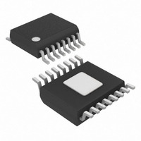
ISL28272FAZ-T7 Intersil, ISL28272FAZ-T7 Datasheet - Page 10

ISL28272FAZ-T7
Manufacturer Part Number
ISL28272FAZ-T7
Description
IC INSTR AMP RRIO DUAL 16-QSOP
Manufacturer
Intersil
Datasheet
1.ISL28271INEVAL1Z.pdf
(14 pages)
Specifications of ISL28272FAZ-T7
Amplifier Type
Instrumentation
Number Of Circuits
2
Output Type
Rail-to-Rail
Slew Rate
0.5 V/µs
-3db Bandwidth
100kHz
Current - Input Bias
10pA
Voltage - Input Offset
35µV
Current - Supply
120µA
Current - Output / Channel
31mA
Voltage - Supply, Single/dual (±)
2.4 V ~ 5.5 V, ±1.2 V ~ 2.75 V
Operating Temperature
-40°C ~ 125°C
Mounting Type
Surface Mount
Package / Case
16-QSOP
Lead Free Status / RoHS Status
Lead free / RoHS Compliant
Gain Bandwidth Product
-
Other names
ISL28272FAZ-T7
ISL28272FAZ-T7TR
ISL28272FAZ-T7TR
Pin Descriptions
16 Ld QSOP
ISL28271
FB-
2, 15
3, 14
4, 13
5, 12
6, 11
7, 10
IN-
1, 9
16
FB-
8
IN-
CIRCUIT 1A
CIRCUIT 1B
16 Ld QSOP
ISL28272
2, 15
3, 14
4, 13
5, 12
7, 10
6, 11
1, 9
16
8
V
IN+
FB+
V
+
-
10
V
V
IN+
FB+
PIN NAME
+
-
OUT_A,
OUT_B
FB+_A,
FB+_B
FB-_A,
IN+_A,
EN_A,
FB-_B
IN-_A,
IN+_B
EN_B
IN-_B
NC
V+
V-
LOGIC
PIN
EQUIVALENT
Circuit 1A,
Circuit 1A,
Circuit 1A,
Circuit 1A,
Circuit 1B
Circuit 1B
Circuit 1B
Circuit 1B
CIRCUIT
Circuit 3
Circuit 2
Circuit 4
Circuit 4
CIRCUIT 2
ISL28271, ISL28272
Output Voltage. A complementary Class AB common-source output stage drives
the output of each channel. When disabled, the outputs are in a high impedance
state.
Positive Feedback high impedance terminals. ISL28272 input circuit is shown in
Circuit 1A, and the ISL28271 input circuit is shown in Circuit 1B.
ISL28271: to avoid offset drift, it is recommended that the terminals of the
ISL28271 are not overdriven beyond 1V and the input current must never
exceed 5mA.
Negative Feedback high impedance terminals. The FB- pins connect to an
external resistor divider to individually set the desired gain of the in-amp.
ISL28272 input circuit is shown in Circuit 1A, and the ISL28271 input circuit is
shown in Circuit 1B.
ISL28271: to avoid offset drift, it is recommended that the terminals of the
ISL28271 are not overdriven beyond 1V and the input current must never
exceed 5mA.
High impedance Inverting input terminals. Connect to the low side of the input
source signal. ISL28272 input circuit is shown in Circuit 1A, and the ISL28271
input circuit is shown in Circuit 1B.
ISL28271: to avoid offset drift, it is recommended that the terminals of the
ISL28271 are not overdriven beyond 1V and the input current must never
exceed 5mA.
High impedance Non-inverting input terminals. Connect to the high side of the
input source signal. ISL28272 input circuit is shown in Circuit 1A, and the
ISL28271 input circuit is shown in Circuit 1B.
ISL28271: to avoid offset drift, it is recommended that the terminals of the
ISL28271 are not overdriven beyond 1V and the input current must never
exceed 5mA.
Active LOW logic pins. When pulled above 2V, the corresponding channel turns
off and OUT is high impedance. A channel is enabled when pulled below 0.8V.
Built-in pull downs define each EN pin LOW when left floating.
Positive Supply terminal shared by all channels.
Negative Supply terminal shared by all channels. Grounded for single supply
operation.
No Connect, pins can be left floating or grounded.
V
V
-
+
CIRCUIT 3
V
OUT
V
PIN FUNCTION
-
+
V
V
+
-
CIRCUIT 4
CAPACITIVELY
COUPLED
ESD CLAMP
August 17, 2007
FN6390.2


