MC33179PG ON Semiconductor, MC33179PG Datasheet - Page 14
MC33179PG
Manufacturer Part Number
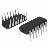
MC33179PG
Description
IC OPAMP QUAD LP LO NOISE 14DIP
Manufacturer
ON Semiconductor
Datasheet
1.MC33178PG.pdf
(19 pages)
Specifications of MC33179PG
Amplifier Type
General Purpose
Number Of Circuits
4
Slew Rate
2 V/µs
Gain Bandwidth Product
5MHz
Current - Input Bias
100nA
Voltage - Input Offset
1500µV
Current - Supply
1.7mA
Current - Output / Channel
100mA
Voltage - Supply, Single/dual (±)
4 V ~ 36 V, ±2 V ~ 18 V
Operating Temperature
-40°C ~ 85°C
Mounting Type
Through Hole
Package / Case
14-DIP (0.300", 7.62mm)
Number Of Channels
4
Common Mode Rejection Ratio (min)
80 dB
Input Voltage Range (max)
Positive Rail - 2 V
Input Voltage Range (min)
Negative Rail + 2 V
Input Offset Voltage
3 mV
Input Bias Current (max)
500 nA
Operating Supply Voltage
36 V
Supply Current
1.7 mA
Maximum Operating Temperature
+ 85 C
Minimum Operating Temperature
- 40 C
Dual Supply Voltage
+/- 3 V, +/- 5 V, +/- 9 V
Maximum Dual Supply Voltage
+/- 18 V
Minimum Dual Supply Voltage
+/- 2 V
Mounting Style
Through Hole
Shutdown
No
Technology
Bipolar
Voltage Gain Db
106.02 dB
Lead Free Status / RoHS Status
Lead free / RoHS Compliant
Output Type
-
-3db Bandwidth
-
Lead Free Status / Rohs Status
Lead free / RoHS Compliant
Other names
MC33179PGOS
Available stocks
Company
Part Number
Manufacturer
Quantity
Price
Company:

Part Number:
MC33179PG
Manufacturer:
ON Semiconductor
Quantity:
3 150


−T−
0.038 (0.0015)
SEATING
PLANE
PIN 1 ID
H
E
e
D D
A1
A
b
*For additional information on our Pb−Free strategy and soldering
E
details, please download the ON Semiconductor Soldering and
Mounting Techniques Reference Manual, SOLDERRM/D.
8 PL
0.08 (0.003)
8X
c
0.041
1.04
6X
M
0.0256
0.126
0.65
3.20
SOLDERING FOOTPRINT*
T
B
http://onsemi.com
S
CASE 846A−02
A
Micro8t
ISSUE G
L
S
14
0.015
0.38
8X
0.167
SCALE 8:1
4.24
NOTES:
1. DIMENSIONING AND TOLERANCING PER ANSI Y14.5M, 1982.
2. CONTROLLING DIMENSION: MILLIMETER.
3. DIMENSION A DOES NOT INCLUDE MOLD FLASH, PROTRUSIONS OR GATE
4. DIMENSION B DOES NOT INCLUDE INTERLEAD FLASH OR PROTRUSION.
5. 846A−01 OBSOLETE, NEW STANDARD 846A−02.
BURRS. MOLD FLASH, PROTRUSIONS OR GATE BURRS SHALL NOT EXCEED
0.15 (0.006) PER SIDE.
INTERLEAD FLASH OR PROTRUSION SHALL NOT EXCEED 0.25 (0.010) PER SIDE.
DIM
H
A1
A
b
c
D
E
e
L
E
0.208
5.28
inches
MIN
0.05
0.25
0.13
2.90
2.90
0.40
4.75
mm
−−
MILLIMETERS
0.65 BSC
NOM
0.08
0.33
0.18
3.00
3.00
0.55
4.90
−−
MAX
1.10
0.15
0.40
0.23
3.10
3.10
0.70
5.05
0.002
0.010
0.005
0.016
0.187
0.114
0.114
MIN
−−
0.026 BSC
INCHES
0.003
0.013
0.007
0.021
0.193
NOM
0.118
0.118
−−
0.043
0.006
0.016
0.009
0.122
0.122
0.028
0.199
MAX
Related parts for MC33179PG
Image
Part Number
Description
Manufacturer
Datasheet
Request
R

Part Number:
Description:
ON Semiconductor [VOLTAGE REGULATOR]
Manufacturer:
ON Semiconductor
Datasheet:
Part Number:
Description:
357-036-542-201 CARDEDGE 36POS DL .156 BLK LOPRO
Manufacturer:
ON Semiconductor
Datasheet:
Part Number:
Description:
357-036-542-201 CARDEDGE 36POS DL .156 BLK LOPRO
Manufacturer:
ON Semiconductor
Datasheet:
Part Number:
Description:
357-036-542-201 CARDEDGE 36POS DL .156 BLK LOPRO
Manufacturer:
ON Semiconductor
Datasheet:
Part Number:
Description:
357-036-542-201 CARDEDGE 36POS DL .156 BLK LOPRO
Manufacturer:
ON Semiconductor
Datasheet:
Part Number:
Description:
357-036-542-201 CARDEDGE 36POS DL .156 BLK LOPRO
Manufacturer:
ON Semiconductor
Datasheet:
Part Number:
Description:
357-036-542-201 CARDEDGE 36POS DL .156 BLK LOPRO
Manufacturer:
ON Semiconductor
Datasheet:
Part Number:
Description:
357-036-542-201 CARDEDGE 36POS DL .156 BLK LOPRO
Manufacturer:
ON Semiconductor
Datasheet:
Part Number:
Description:
357-036-542-201 CARDEDGE 36POS DL .156 BLK LOPRO
Manufacturer:
ON Semiconductor
Datasheet:
Part Number:
Description:
357-036-542-201 CARDEDGE 36POS DL .156 BLK LOPRO
Manufacturer:
ON Semiconductor
Datasheet:
Part Number:
Description:
357-036-542-201 CARDEDGE 36POS DL .156 BLK LOPRO
Manufacturer:
ON Semiconductor
Datasheet:
Part Number:
Description:
Manufacturer:
ON Semiconductor
Datasheet:
Part Number:
Description:
Manufacturer:
ON Semiconductor
Datasheet:
Part Number:
Description:
Manufacturer:
ON Semiconductor
Datasheet: