MC33179PG ON Semiconductor, MC33179PG Datasheet - Page 9
MC33179PG
Manufacturer Part Number
MC33179PG
Description
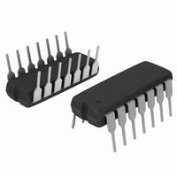
IC OPAMP QUAD LP LO NOISE 14DIP
Manufacturer
ON Semiconductor
Datasheet
1.MC33178PG.pdf
(19 pages)
Specifications of MC33179PG
Amplifier Type
General Purpose
Number Of Circuits
4
Slew Rate
2 V/µs
Gain Bandwidth Product
5MHz
Current - Input Bias
100nA
Voltage - Input Offset
1500µV
Current - Supply
1.7mA
Current - Output / Channel
100mA
Voltage - Supply, Single/dual (±)
4 V ~ 36 V, ±2 V ~ 18 V
Operating Temperature
-40°C ~ 85°C
Mounting Type
Through Hole
Package / Case
14-DIP (0.300", 7.62mm)
Number Of Channels
4
Common Mode Rejection Ratio (min)
80 dB
Input Voltage Range (max)
Positive Rail - 2 V
Input Voltage Range (min)
Negative Rail + 2 V
Input Offset Voltage
3 mV
Input Bias Current (max)
500 nA
Operating Supply Voltage
36 V
Supply Current
1.7 mA
Maximum Operating Temperature
+ 85 C
Minimum Operating Temperature
- 40 C
Dual Supply Voltage
+/- 3 V, +/- 5 V, +/- 9 V
Maximum Dual Supply Voltage
+/- 18 V
Minimum Dual Supply Voltage
+/- 2 V
Mounting Style
Through Hole
Shutdown
No
Technology
Bipolar
Voltage Gain Db
106.02 dB
Lead Free Status / RoHS Status
Lead free / RoHS Compliant
Output Type
-
-3db Bandwidth
-
Lead Free Status / Rohs Status
Lead free / RoHS Compliant
Other names
MC33179PGOS
Available stocks
Company
Part Number
Manufacturer
Quantity
Price
Company:

Part Number:
MC33179PG
Manufacturer:
ON Semiconductor
Quantity:
3 150


0.01
60
50
40
30
20
10
9.0
6.0
3.0
1.0
0.1
18
15
12
10
0
0
−55
10
10
Figure 24. Open Loop Gain Margin and Phase
V
V
R
V
Margin versus Output Load Capacitance
CC
EE
L
in
= 600 W
Figure 26. Total Harmonic Distortion
= −15 V T
= +15 V V
−25
−
+
C
L
V
V
R
, OUTPUT LOAD CAPACITANCE (pF)
600 W
100
T
CC
EE
L
Figure 22. Phase Margin
A
A
O
= 600 W
, AMBIENT TEMPERATURE (°C)
= 25°C
versus Frequency
= 2.0 V
= −15 V
= +15 V
versus Temperature
0
f, FREQUENCY (Hz)
pp
Phase Margin
C
25
L
Gain Margin
V
1.0 k
100
O
A
V
A
A
= 100
V
V
= 10
= 1000
50
C
L
C
C
= 100 pF
L
L
= 300 pF
= 10 pF
A
V
V
V
V
75
10 k
CC
EE
O
= 1.0
= 0 V
= −15 V
= +15 V
100
http://onsemi.com
1.0 k
100 k
60
50
40
30
20
10
0
125
9
8.0
6.0
4.0
2.0
12
10
150
140
130
120
110
100
0
500
400
300
200
100
100
100
0
1.0 k
V
V
V
R
V
T
in
A
CC
EE
T
O
Figure 23. Phase Margin and Gain Margin
= 25°C
= R
= 0 V
= −15 V
= +15 V
versus Differential Source Resistance
R
1
1. A
2. A
3. A
4. A
T
R
+R
R
, DIFFERENTIAL SOURCE RESISTANCE (W)
3
2
1
2
V
V
V
V
Figure 25. Channel Separation
4
= 1.0
= 10
= 100
= 1000
1.0 k
Figure 27. Output Impedance
10 k
−
+
1.0 k
versus Frequency
versus Frequency
f, FREQUENCY (Hz)
f, FREQUENCY (Hz)
V
O
100 k
10 k
2
10 k
Gain Margin
Phase Margin
100 k
1.0 M
Drive Channel
V
C
R
T
A
CC
EE
L
V
V
V
T
1
= 25°C
A
= 600 W
CC
EE
O
= +15 V
= −15 V
= 25°C
= 0 V
= +15 V
= −15 V
100 k
60
50
40
30
20
10
0
1.0 M
10 M
Related parts for MC33179PG
Image
Part Number
Description
Manufacturer
Datasheet
Request
R

Part Number:
Description:
ON Semiconductor [VOLTAGE REGULATOR]
Manufacturer:
ON Semiconductor
Datasheet:
Part Number:
Description:
357-036-542-201 CARDEDGE 36POS DL .156 BLK LOPRO
Manufacturer:
ON Semiconductor
Datasheet:
Part Number:
Description:
357-036-542-201 CARDEDGE 36POS DL .156 BLK LOPRO
Manufacturer:
ON Semiconductor
Datasheet:
Part Number:
Description:
357-036-542-201 CARDEDGE 36POS DL .156 BLK LOPRO
Manufacturer:
ON Semiconductor
Datasheet:
Part Number:
Description:
357-036-542-201 CARDEDGE 36POS DL .156 BLK LOPRO
Manufacturer:
ON Semiconductor
Datasheet:
Part Number:
Description:
357-036-542-201 CARDEDGE 36POS DL .156 BLK LOPRO
Manufacturer:
ON Semiconductor
Datasheet:
Part Number:
Description:
357-036-542-201 CARDEDGE 36POS DL .156 BLK LOPRO
Manufacturer:
ON Semiconductor
Datasheet:
Part Number:
Description:
357-036-542-201 CARDEDGE 36POS DL .156 BLK LOPRO
Manufacturer:
ON Semiconductor
Datasheet:
Part Number:
Description:
357-036-542-201 CARDEDGE 36POS DL .156 BLK LOPRO
Manufacturer:
ON Semiconductor
Datasheet:
Part Number:
Description:
357-036-542-201 CARDEDGE 36POS DL .156 BLK LOPRO
Manufacturer:
ON Semiconductor
Datasheet:
Part Number:
Description:
357-036-542-201 CARDEDGE 36POS DL .156 BLK LOPRO
Manufacturer:
ON Semiconductor
Datasheet:
Part Number:
Description:
Manufacturer:
ON Semiconductor
Datasheet:
Part Number:
Description:
Manufacturer:
ON Semiconductor
Datasheet:
Part Number:
Description:
Manufacturer:
ON Semiconductor
Datasheet: