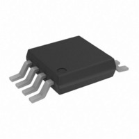
AD8275BRMZ Analog Devices Inc, AD8275BRMZ Datasheet - Page 11

AD8275BRMZ
Manufacturer Part Number
AD8275BRMZ
Description
IC AMP DIFF R-R LDRIFT 8MSOP
Manufacturer
Analog Devices Inc
Datasheet
1.AD8275BRMZ-R7.pdf
(16 pages)
Specifications of AD8275BRMZ
Amplifier Type
Differential
Number Of Circuits
1
Output Type
Rail-to-Rail
Slew Rate
25 V/µs
-3db Bandwidth
15MHz
Voltage - Input Offset
150µV
Current - Supply
1.9mA
Current - Output / Channel
30mA
Voltage - Supply, Single/dual (±)
3.3 V ~ 15 V
Operating Temperature
-40°C ~ 85°C
Mounting Type
Surface Mount
Package / Case
8-MSOP, Micro8™, 8-uMAX, 8-uSOP,
No. Of Amplifiers
1
Input Offset Voltage
500µV
Bandwidth
15MHz
Supply Voltage Range
3.3V To 15V
Supply Current
1.9mA
Amplifier Case Style
MSOP
No. Of Pins
8
Rohs Compliant
Yes
Lead Free Status / RoHS Status
Lead free / RoHS Compliant
Gain Bandwidth Product
-
Current - Input Bias
-
Available stocks
Company
Part Number
Manufacturer
Quantity
Price
Part Number:
AD8275BRMZ
Manufacturer:
ADI/亚德诺
Quantity:
20 000
Company:
Part Number:
AD8275BRMZ-R7
Manufacturer:
Analog Devices Inc
Quantity:
1 793
Company:
Part Number:
AD8275BRMZ-R7
Manufacturer:
LT
Quantity:
2 346
THEORY OF OPERATION
The AD8275 level translates ±10 V signals at its inputs to 4 V
at its output. It does this by attenuating the input signal by 5.
A subtractor network performs the attenuation, the level shifting,
and the differential-to-single-ended conversion. One benefit of
the subtractor topology is that it can accept input signals
beyond its supply voltage. The subtractor is composed of tightly
matched resistors. By integrating the resistors and trimming the
resistor ratios, the AD8275 achieves 80 dB CMRR and 0.024%
gain error.
To achieve a wider input voltage range, the AD8275 uses an
internal 2.5 V voltage bias tied to –V
shown in Figure 31. The resistors help to set the common mode
of the internal amplifier. The benefit of this circuit is that it
extends the input range without causing crossover distortion
typical of amplifiers that have rail-to-rail complementary
transistor inputs. The input range of the internal op amp is
+V
Figure 32. AD8275 Does Not Have Crossover Distortion Typical of Rail-to-Rail
S
− 0.9 V to −V
–200
–400
–600
600
400
200
0
–10
–IN
+IN
–8
Figure 31. AD8275 Simplified Schematic
INPUT
INPUT
ESD
ESD
S
–6
+ 1.35 V.
–V
S
COMMON-MODE VOLTAGE (V)
50kΩ
2.5V
50kΩ
7kΩ
7kΩ
–4
Input Amplifiers
–2
–V
–V
S
S
10kΩ
20kΩ
20kΩ
+V
0
–V
S
S
S
and two 7 kΩ resistors, as
+V
+V
+V
2
–V
S
S
S
S
+V
–V
+V
+V
–V
–V
4
S
S
S
S
S
S
SENSE
OUT
REF2
REF1
6
8
10
Rev. A | Page 11 of 16
The AD8275 employs a balanced, high gain, linear output stage
that adaptively generates current as required, eliminating the
dynamic errors found in other amplifiers. This is useful when
driving SAR ADCs, which can deliver kickback current into the
output of the amplifier. The result is a design that achieves low
distortion, consistent bandwidth, and high slew rate.
BASIC CONNECTION
The basic configurations for the AD8275 are shown in
Figure 33 and Figure 34. In Figure 33, REF1 and REF2 are
tied together. A voltage, V
REF2 pins, sets the output voltage level to V
in Figure 33, if V
the output remains at 2 V.
In contrast, Figure 34 shows REF1 tied to ground and REF2
tied to V
resistor divider, and V
inputs of the AD8275 are grounded and V
is 2.5 V.
REF
V
OUT
Figure 33. Basic Configuration 1: Shared Reference
. In this example, the two 20 kΩ resistors serve as a
V
Figure 34. Basic Configuration 2: Split Reference
V
V
OUT
=
INN
INP
V
V
=
INN
INP
(V
REF
2
3
INP
+IN
AD8275
–IN
(V
2
3
50kΩ
= 2 V and the inputs are tied to ground,
50kΩ
) – (V
AD8275
5
INP
–IN
+IN
REF
+5V
50kΩ
50kΩ
) – (V
5
INN
+5V
is divided by 2. For example, if both
REF
)
+V
–V
INN
7
4
S
S
+ V
10kΩ
, applied to the tied REF1 and
20kΩ
20kΩ
+V
–V
)
4
7
S
REF
S
10kΩ
20kΩ
20kΩ
+
SENSE
REF2
REF1
OUT
V
0.1µF
SENSE
REF
REF2
REF1
OUT
0.1µF
2
+ 0V
5
6
8
1
5
6
8
1
REF
V
REF
REF
= 5 V, the output
. For example,
V
REF
V
OUT
V
AD8275
OUT


