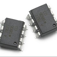
ACPL-782T-000E Avago Technologies US Inc., ACPL-782T-000E Datasheet - Page 16

ACPL-782T-000E
Manufacturer Part Number
ACPL-782T-000E
Description
OPTO AMP ISOLATION AUTO 8-DIP
Manufacturer
Avago Technologies US Inc.
Series
R2Coupler™r
Datasheet
1.ACPL-782T-000E.pdf
(18 pages)
Specifications of ACPL-782T-000E
Package / Case
8-DIP (0.300", 7.62mm)
Mounting Type
Through Hole
Current - Supply
10.86mA
Operating Temperature
-40°C ~ 125°C
Output Type
Differential
Number Of Circuits
1
Current - Output / Channel
18.6mA
Amplifier Type
Isolation
Voltage - Supply, Single/dual (±)
4.5 V ~ 5.5 V
-3db Bandwidth
100kHz
Voltage - Input Offset
300µV
Forward Current
16 mA
Isolation Voltage
3.75 KV
Mounting Style
Through Hole
Number Of Channels
1
Power Dissipation
600 mW
Bandwidth
100 KHz
Input Offset Voltage
0.3 mV
Operating Supply Voltage
4.5 V to 5.5 V
Supply Current
16 mA
Operating Temperature Range
- 40 C to + 125 C
No. Of Amplifiers
1
Gain Non-linearity Max
2%
Slew Rate
1500V/µs
Supply Voltage Range
4.5V To 5.5V
Rohs Compliant
Yes
Lead Free Status / RoHS Status
Lead free / RoHS Compliant
Slew Rate
-
Gain Bandwidth Product
-
Current - Input Bias
-
Lead Free Status / Rohs Status
Lead free / RoHS Compliant
Available stocks
Company
Part Number
Manufacturer
Quantity
Price
Company:
Part Number:
ACPL-782T-000E
Manufacturer:
AVAGO
Quantity:
5 000
Also, multiple layers of the PC board can be used to
increase current carrying capacity. Numerous plated-
through vias should surround each non-Kelvin terminal of
the sense resistor to help distribute the current between
the layers of the PC board. The PC board should use 2 or
4 oz. copper for the layers, resulting in a current carrying
capacity in excess of 20 A.
Note: Please refer to Avago Technologies Application Note 1078 for
additional information on using Isolation Amplifiers.
Sense Resistor Connections
The recommended method for connecting the ACPL-782T
to the current sensing resistor is shown in Figure 18. V
(pin 2 of the APCL-782T) is connected to the positive
terminal of the sense resistor, while VIN- (pin 3) is shorted
to GND1 (pin 4), with the power-supply return path func-
tioning as the sense line to the negative terminal of the
current sense resistor. This allows a single pair of wires
or PC board traces to connect the ACPL-782T circuit to
the sense resistor. By referencing the input circuit to
the negative side of the sense resistor, any load current
induced noise transients on the resistor are seen as a
common-mode signal and will not interfere with the cur-
rent-sense signal. This is important because the large load
currents flowing through the motor drive, along with the
parasitic inductances inherent in the wiring of the circuit,
can generate both noise spikes and offsets that are rela-
tively large compared to the small voltages that are being
measured across the current sensing resistor.
If the same power supply is used both for the gate
drive circuit and for the current sensing circuit, it is
very important that the connection from GND1 of the
ACPL-782T to the sense resistor be the only return path for
Figure 21. Recommended circuit for voltage sensing application.
16
Line 1
Line 2
Ra
Rb
+ SUPPLY
0.1 PF
Note for the Voltage Divider:
V (Line) x [ Rb / (Ra+Rb) ] <= 200 mV
IN
78L05
39 :
OUT
+5 V
0.1 PF
0.01
PF
1
3
4
2
ACPL-782T
IN+
8
7
6
5
supply current to the gate drive power supply in order to
eliminate potential ground loop problems. The only direct
connection between the ACPL-782T circuit and the gate
drive circuit should be the positive power supply line.
Output Side
The op-amp used in the external post-amplifier circuit
should be of sufficiently high precision so that it does not
contribute a significant amount of offset or offset drift
relative to the contribution from the isolation amplifier.
Generally, op-amps with bipolar input stages exhibit
better offset performance than op-amps with JFET or
MOSFET input stages.
In addition, the op-amp should also have enough
bandwidth and slew rate so that it does not adversely
affect the response speed of the overall circuit. The post-
amplifier circuit includes a pair of capacitors (C5 and C6)
that form a single-pole low-pass filter; these capacitors
allow the bandwidth of the post-amp to be adjusted
independently of the gain and are useful for reducing
the output noise from the isolation amplifier. Many
different op-amps could be used in the circuit, including:
TL032A, TL052A, and TLC277 (Texas Instruments), LF412A
(National Semiconductor).
The gain-setting resistors in the post-amp should have a
tolerance of 1% or better to ensure adequate CMRR and
adequate gain tolerance for the overall circuit. Resistor
networks can be used that have much better ratio
tolerances than can be achieved using discrete resistors.
A resistor network also reduces the total number of
components for the circuit as well as the required board
space.
+5 V
0.1 PF
150 pF
2.0 k:
2.00 k:
10.0 k:
+15 V
6
5
+
-
-15 V
8
4
10.0 k:
150 pF
TL032A
0.1 PF
0.1 PF
7
V
OUT


