PA78EU Cirrus Logic Inc, PA78EU Datasheet - Page 8
PA78EU
Manufacturer Part Number
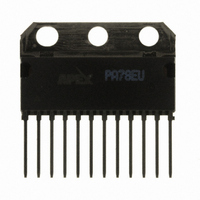
PA78EU
Description
IC PWR AMP 350V 200MA 12SIP
Manufacturer
Cirrus Logic Inc
Series
Apex Precision Power™r
Specifications of PA78EU
Amplifier Type
Power
Number Of Circuits
1
Slew Rate
350 V/µs
Gain Bandwidth Product
1MHz
Current - Input Bias
8.5pA
Voltage - Input Offset
8000µV
Current - Supply
700µA
Current - Output / Channel
150mA
Voltage - Supply, Single/dual (±)
20 V ~ 350 V, ±10 V ~ 175 V
Operating Temperature
-40°C ~ 125°C
Mounting Type
Through Hole
Package / Case
12-SIP
For Use With
598-1398 - KIT EVALUATION PA78/PA79598-1395 - EVALUATION KIT FOR PA78
Lead Free Status / RoHS Status
Lead free / RoHS Compliant
Output Type
-
-3db Bandwidth
-
Other names
598-1440
PA78EU
PA78EU
Available stocks
Company
Part Number
Manufacturer
Quantity
Price

Part Number:
PA78EU
Manufacturer:
APEX
Quantity:
20 000


PA78
8
GENERAL
Please read Application note 1 “General operating
considerations” which covers stability, power sup-
plies, heat sinking, mounting, current limit, SOA inter-
pretation, and specification interpretation. Visit www.
cirrus.com for design tools that help automate tasks
such as calculations for stability, internal power dis-
sipation, and current limit. There you will also find a
complete application notes library, technical seminar
workbook, and evaluation kits.
ThEORY OF OPERATION
The PA78 is designed specifically as a high speed
pulse amplifier. In order to achieve high slew rates
with low idle current, the internal design is quite dif-
ferent from traditional voltage feedback amplifiers.
Basic op amp behaviors like high input impedance
and high open loop gain still apply. But there are
some notable differences, such as signal dependent
supply current, bandwidth and output impedance,
among others. The impact of these differences var-
ies depending on application performance require-
ments and circumstances. These different behaviors
are ideal for some applications but can make designs
more challenging in other circumstances.
SUPPLY CURRENT AND BYPASS CAPACITANCE
A traditional voltage feedback amplifier relies on fixed current sources in each stage to drive the parasitic capaci-
tances of the next stage. These currents combine to define the idle or quiescent current of the amplifier. By design,
these fixed currents are often the limiting parameter for slew rate and bandwidth of the amplifier. Amplifiers which
are high voltage and have fast slew rates typically have high idle currents and dissipate notable power with no sig-
nal applied to the load. At the heart of the PA78 design is a signal dependent current source which strikes a new
balance between supply current and dynamic performance. With small input signals, the supply current of the PA78
is very low, idling at less than 1 mA. With large transient input signals, the supply currents increase dramatically to
allow the amplifier stages to respond quickly. The Pulse Response plot in the typical performance section of this
datasheet describes the dynamic nature of the supply current with various input transients.
Choosing proper bypass capacitance requires careful consideration of the dynamic supply currents. High frequency
ceramic capacitors of 0.1µF or more should be placed as close as possible to the amplifier supply pins. The in-
ductance of the routing from the supply pins to these ceramic capacitors will limit the supply of peak current during
transients, thus reducing the slew rate of the PA78. The high frequency capacitance should be supplemented by
additional bypass capacitance not more than a few centimeters from the amplifier. This additional bypass can be
a slower capacitor technology, such as electrolytic, and is necessary to keep the supplies stable during sustained
output currents. Generally, a few microfarad is sufficient.
SMALL SIGNAL PERFORMANCE
The small signal performance plots in the typical performance section of this datasheet describe the behavior when
the dynamic current sources described previously are near the idle state. The selection of compensation capacitor
directly affects the open loop gain and phase performance.
Depending on the configuration of the amplifier, these plots show that the phase margin can diminish to very low
levels when left uncompensated. This is due to the amount of bias current in the input stage when the part is in
P r o d u c t I n n o v a t i o n F r o m
1200
1000
1600
1400
1200
1000
800
600
400
200
800
600
400
200
0
0
0
0
R
R
R
V
C
R
R
R
V
C
S
S
F
G
L
L
F
G
L
L
1
1
= 75K
= 50K
= ±150V
= 8pF
= 75K
= 50K
= ±150V
= 8pF
= 1.5K
= 1.5K
2
2
INPUT VOLTAGE, VOLTS PEAK-TO-PEAK
3
3
PEAK TO PEAK INPUT VOLTAGE
4
4
SR+(A
SR-(A
SR+(A
SR-(A
SR+/SR- (25%-75%)
SR+/SR- (25%-75%)
5
5
6
6
V
V
V
V
= -25)
= +26)
= -25)
= +26)
7
7
8
8
9
9
10 11 12 13 14 15
10 11 12 13 14 15
SR+(A
SR-(A
SR+(A
SR-(A
V
V
V
V
= -50)
= +51)
= -50)
= +51)
PA78U
Related parts for PA78EU
Image
Part Number
Description
Manufacturer
Datasheet
Request
R

Part Number:
Description:
Development Kit
Manufacturer:
Cirrus Logic Inc
Datasheet:
Part Number:
Description:
Development Kit
Manufacturer:
Cirrus Logic Inc
Datasheet:


Part Number:
Description:
High-efficiency PFC + Fluorescent Lamp Driver Reference Design
Manufacturer:
Cirrus Logic Inc
Datasheet:
Part Number:
Description:
Development Kit
Manufacturer:
Cirrus Logic Inc
Datasheet:
Part Number:
Description:
Development Kit
Manufacturer:
Cirrus Logic Inc
Datasheet:

Part Number:
Description:
Development Kit
Manufacturer:
Cirrus Logic Inc
Datasheet:
Part Number:
Description:
Development Kit
Manufacturer:
Cirrus Logic Inc
Datasheet:
Part Number:
Description:
Development Kit
Manufacturer:
Cirrus Logic Inc
Datasheet:
Part Number:
Description:
Development Kit
Manufacturer:
Cirrus Logic Inc
Datasheet:

Part Number:
Description:
EVALUATION BOARD FOR CS8427
Manufacturer:
Cirrus Logic Inc
Datasheet:

Part Number:
Description:
BOARD EVAL FOR CS8416 RCVR
Manufacturer:
Cirrus Logic Inc
Datasheet:

Part Number:
Description:
EVALUATION BOARD FOR CS8420
Manufacturer:
Cirrus Logic Inc
Datasheet:

Part Number:
Description:
KIT DEVELOPMENT EP9315 ARM9
Manufacturer:
Cirrus Logic Inc
Datasheet:

Part Number:
Description:
KIT DEVELOPMENT EP9302 ARM9
Manufacturer:
Cirrus Logic Inc
Datasheet: