PA78EU Cirrus Logic Inc, PA78EU Datasheet
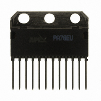
IC PWR AMP 350V 200MA 12SIP

PA78EU

Manufacturer Part Number
PA78EU
Description
IC PWR AMP 350V 200MA 12SIP
Manufacturer
Cirrus Logic Inc
Series
Apex Precision Power™r
Datasheets

Specifications of PA78EU

Amplifier Type
Power
Number Of Circuits
1
Slew Rate
350 V/µs
Gain Bandwidth Product
1MHz
Current - Input Bias
8.5pA
Voltage - Input Offset
8000µV
Current - Supply
700µA
Current - Output / Channel
150mA
Voltage - Supply, Single/dual (±)
20 V ~ 350 V, ±10 V ~ 175 V
Operating Temperature
-40°C ~ 125°C
Mounting Type
Through Hole
Package / Case
12-SIP
For Use With
598-1398 - KIT EVALUATION PA78/PA79598-1395 - EVALUATION KIT FOR PA78
Lead Free Status / RoHS Status
Lead free / RoHS Compliant
Output Type
-
-3db Bandwidth
-
Other names
598-1440
PA78EU

Available stocks

Company
Part Number
Manufacturer
Quantity
Price
Part Number:
PA78EU
Manufacturer:
MOT
Quantity:
10
Part Number:
PA78EU
Manufacturer:
APEX
Quantity:
20 000
M I C R O T E C H N O L O G Y
I. INTRODuCTION
made demands upon operational power amplifiers for higher
speed and low power dissipation. These devices can produce
motions in sub-nanometer increments and are extraordinarily
fast, responding to any change in the applied voltage in just
microseconds.
as other circuitry requiring high-power, fast slew-rate drivers,
Apex Microtechnology developed the PA78 power operational
amplifier. This IC employs a unique patented circuit and a first
for a commercially-available power operational amplifier.
fixed current sources, such as I
Because the sources are fixed, they limit the slew rate and
dissipate a good deal of power. What makes the PA78 unique
is that in addition to its fixed current sources, it employs the
dynamic current sources depicted in Figure 1. Consequently,
in addition to its normal role of driving the output, the waveform
applied at the input of the PA78 also causes the dynamic
current sources to supply the necessary current to sink and
Figure 1. Dynamic Current Sources Dramatically Enhance Performance — Providing the instantaneous currents necessary to
achieve high slew rates, yet current consumption at one milliampere when idle, is extremely low.
APEX MICROTECHNOLOGY CORPORATION • TELEPHONE (520) 690-8600 • FAX (520) 888-3329 • ORDERS (520) 690-8601 • EMAIL prodlit@apexmicrotech.com
The rapidly expanding interest in piezoelectric actuators has
To meet the requirements of piezoelectric designs, as well
In a traditional power operational amplifier there are several
1
and I
2
, shown in Figure 1.
PA78 DESIGN IDEAS
source the device capacitances. This enables the output
MOSFETs Q
volts per microsecond. What's more, whenever the PA78 is
idle, its quiescent current is very low – less than 2.5 milliam-
pere — so even when powered by 350 volts, the quiescent
power is less than a watt. This is far less than traditional power
operational amplifiers in a comparable circuit. What follows
are three circuits that have been developed to fulfill various
roles in piezoelectric designs.
9
and Q
10
to achieve slew rates as high as 350
1

Related parts for PA78EU

PA78EU Summary of contents

Page 1

INTRODuCTION The rapidly expanding interest in piezoelectric actuators has made demands upon operational power amplifiers for higher speed and low power dissipation. These devices ...

Page 2

Figure 2. Bridge Connected – A pair of PA78s drive the piezoelectric actuator and are powered by asymmetric power supplies at +175V and -5V. II. BRIDGE-CONNECTED PIEZOELECTRIC ACTuATOR DRIvER A piezoelectric actuator requires a high-voltage driver ca- pable of delivering ...

Page 3

Figure 3. Output Waveforms – a) Left module output; b) Right module output; C) Waveform appearing across the piezoelectric actuator. What follows is a discussion of the principal passive com- ponents: R and R — The feedback circuit comprising resistors ...

Page 4

Computing the maximum dissipated power per module — The load impedance of the piezoelectric actuator is given by the expression: ω To compute the maximum power per module the equiva- lent circuit shown in Figure 4 is employed. By doing ...

Page 5

III. DRIvING DEFLECTION PLATES The circuit shown in Figure 5 was developed for 'Continuous Drop' printing applications. In this circuit the PA78 power op- erational amplifier connects directly to the deflection plates. Electrostatically-charged ink droplets, typically microns ...

Page 6

Iv. DEFLECTION PLATES DRIvER wITH OvERDRIvE What is different about the circuit shown in Figure 6, com- pared with Figure 5, is that it is assumed that the deflection plates are driven via a 25-foot length of coax that exhibits ...

Related keywords