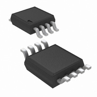
LMH6658MM/NOPB National Semiconductor, LMH6658MM/NOPB Datasheet - Page 17

LMH6658MM/NOPB
Manufacturer Part Number
LMH6658MM/NOPB
Description
IC OPAMP 270MHZ DUAL 8MSOP
Manufacturer
National Semiconductor
Series
PowerWise®r
Datasheet
1.LMH6657MFNOPB.pdf
(20 pages)
Specifications of LMH6658MM/NOPB
Amplifier Type
Voltage Feedback
Number Of Circuits
2
Slew Rate
700 V/µs
Gain Bandwidth Product
140MHz
-3db Bandwidth
270MHz
Current - Input Bias
5µA
Voltage - Input Offset
1000µV
Current - Supply
6.5mA
Current - Output / Channel
110mA
Voltage - Supply, Single/dual (±)
3 V ~ 12 V, ±1.5 V ~ 6 V
Operating Temperature
-40°C ~ 85°C
Mounting Type
Surface Mount
Package / Case
8-MSOP, Micro8™, 8-uMAX, 8-uSOP,
Number Of Channels
2
Voltage Gain Db
95 dB
Common Mode Rejection Ratio (min)
72 dB
Input Offset Voltage
5 mV at 5 V
Operating Supply Voltage
5 V, 9 V
Supply Current
17 mA at 5 V
Maximum Operating Temperature
+ 85 C
Maximum Dual Supply Voltage
+/- 6 V
Minimum Operating Temperature
- 40 C
Lead Free Status / RoHS Status
Lead free / RoHS Compliant
Output Type
-
Lead Free Status / Rohs Status
Details
Other names
LMH6658MM
LMH6658MMTR
LMH6658MMTR
Output Characteristics
with the signal and there is no subsequent ill effects due to
this shift in operating point and the possibility of additional
non-linearity. Moreover, under low closed loop gain settings
(most suited to low distortion), the non-inverting configura-
tion is at a further disadvantage of having to contend with the
input common voltage range. There is also a strong relation-
ship between output loading and distortion performance (i.e.
1kΩ vs. 100Ω distortion improves by about 20dB
especially at the lower frequency end where the distortion
tends to be lower. At higher frequency, this dependence
diminishes greatly such that this difference is only about 4dB
at 10MHz. But, in general, lighter output load leads to re-
duced HD3 term and thus improves THD.
PRINTED CIRCUIT BOARD LAYOUT AND COMPONENT
VALUES SECTIONS
Generally, a good high frequency layout will keep power
supply and ground traces away from the inverting input and
output pins. Parasitic capacitances on these nodes to
ground will cause frequency response peaking and possible
circuit oscillations (see Application Note OA-15 for more
information). National Semiconductor suggests the following
(Continued)
@
100KHz)
17
evaluation boards as a guide for high frequency layout and
as an aid in device testing and characterization:
These free evaluation boards are shipped when a device
sample request is placed with National Semiconductor. An-
other important parameter in working with high speed/high
performance amplifiers, is the component values selection.
Choosing external resistors that are large in value will effect
the closed loop behavior of the stage because of the inter-
action of these resistors with parasitic capacitances. These
capacitors could be inherent to the device or a by-product of
the board layout and component placement. Either way,
keeping the resistor values lower, will diminish this interac-
tion to a large extent. On the other hand, choosing very low
value resistors will load down nodes and will contribute to
higher overall power dissipation.
LMH6657MG
LMH6658MM
LMH6657MF
LMH6658MA
Device
8-Pin MSOP
8-Pin SOIC
Package
SOT23-5
SC-70
CLC730068
CLC730036
CLC730123
Evaluation
Board PN
NA
www.national.com


