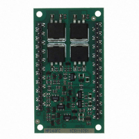
MP240FC Cirrus Logic Inc, MP240FC Datasheet - Page 5

MP240FC
Manufacturer Part Number
MP240FC
Description
IC OPAMP 200V 20A OPEN 42DIP
Manufacturer
Cirrus Logic Inc
Series
Apex Precision Power™r
Datasheet
1.MP240FC.pdf
(7 pages)
Specifications of MP240FC
Package / Case
42-DIP Module
Amplifier Type
Power
Number Of Circuits
1
Slew Rate
14 V/µs
Gain Bandwidth Product
1.8MHz
Current - Input Bias
100pA
Voltage - Input Offset
1000µV
Current - Supply
16.5mA
Current - Output / Channel
20A
Voltage - Supply, Single/dual (±)
30 V ~ 200 V, ±15 V ~ 100 V
Operating Temperature
-40°C ~ 85°C
Mounting Type
Through Hole
Description/function
Audio Amplifiers
Product
Audio Modules
Lead Free Status / RoHS Status
Contains lead / RoHS non-compliant
For Use With
598-1396 - KIT EVAL FOR MP230FC/MP240FC
Output Type
-
-3db Bandwidth
-
Lead Free Status / Rohs Status
Lead free / RoHS Compliant
Other names
598-1411
MP240FC
MP240FC
Available stocks
Company
Part Number
Manufacturer
Quantity
Price
Part Number:
MP240FC
Manufacturer:
APEX
Quantity:
20 000
MP240
P r o d u c t I n n o v a t i o n F r o m
tYPical aPPlication
Motor Position control
The MOSFET output stage of the MP240 pro-
vides superior SOA performance compared
to bipolar output stages where secondary
breakdown is a concern. The extended SOA
is ideal in motor drive applications where the
back EMF of the motor may impose simul-
taneously both high voltage and high current
across the output stage transistors. In the fig-
ure above a mechanical to electrical feedback
position converter allows the MP240 to drive
the motor in either direction to a set point de-
termined by the DAC voltage.
The MP400 is ideally suited to driving both
piezo actuation and deflection applications
off of a single low voltage supply. The circuit
above boosts a system 24V buss to 350V to
drive an ink jet print head. The MP400s high speed deflection amplifier is biased for single supply operation by
external resistors R2 – R6, so that a 0 to 5V DAC can be used as the input to the amplifier to drive the print head
from 0 to >300V.
General
Please read Application Note 1 “General Operating Considerations” which covers stability, power supplies, heat
sinking, mounting, current limit, SOA interpretation, and specification interpretation. Visit www.cirrus.com for design
tools that help automate tasks such as calculations for stability, internal power dissipation, current limit, heat sink
selection, Cirrus’s complete Application Notes library, Technical Seminar Workbook and Evaluation Kits.
GroUnD Pins
The MP240 has two ground pins (pins 2, 40). These pins provide a return for the internal capacitive bypassing of
the small signal stages of the MP240. The two ground pins are not connected together on the substrate. Both of
these pins are required to be connected to the system signal ground.
balancinG resistor selection (r
-r
)
s
s4
The MP240 uses parallel sets of output transistors. To ensure that the load current is evenly shared among the
transistors external balancing resistors R
-R
are required. To calculate the required value for each of the resistors
S1
S4
use: R = 4.5/I
,where I is the maximum expected output current. For example, with a maximum output current of
2
10A each balancing resistor should be 0.045 ohms. Each resistor dissipates 1.125W at the maximum current. Use
a non-inductive 2W rated resistor. A ready source for such resistors is the IRC resistor series LR available from
Mouser Electronics.
saFe oPeratinG area
The MOSFET output stage of the MP240 is not limited by second breakdown considerations as in bipolar output
stages. Only thermal considerations and current handling capabilities limit the SOA (see Safe Operating Area graph
on previous page). The output stage is protected against transient flyback by the parasitic diodes of the output stage
MOSFET structure. However, for protection against sustained high energy flyback external fast-recovery diodes
must be used.
coMPensation
The external compensation capacitor C
is connected to pins 4 and 6. Unity gain stability can be achieved with
C
C
= 680pF for a minimum phase margin of 60 degrees. At higher gains more phase shift can usually be tolerated
C
and C
can be reduced resulting in higher bandwidth and slew rate. Use the typical operating curves as a guide to
C
MP240U


