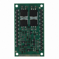
MP240FC Cirrus Logic Inc, MP240FC Datasheet - Page 6

MP240FC
Manufacturer Part Number
MP240FC
Description
IC OPAMP 200V 20A OPEN 42DIP
Manufacturer
Cirrus Logic Inc
Series
Apex Precision Power™r
Datasheet
1.MP240FC.pdf
(7 pages)
Specifications of MP240FC
Package / Case
42-DIP Module
Amplifier Type
Power
Number Of Circuits
1
Slew Rate
14 V/µs
Gain Bandwidth Product
1.8MHz
Current - Input Bias
100pA
Voltage - Input Offset
1000µV
Current - Supply
16.5mA
Current - Output / Channel
20A
Voltage - Supply, Single/dual (±)
30 V ~ 200 V, ±15 V ~ 100 V
Operating Temperature
-40°C ~ 85°C
Mounting Type
Through Hole
Description/function
Audio Amplifiers
Product
Audio Modules
Lead Free Status / RoHS Status
Contains lead / RoHS non-compliant
For Use With
598-1396 - KIT EVAL FOR MP230FC/MP240FC
Output Type
-
-3db Bandwidth
-
Lead Free Status / Rohs Status
Lead free / RoHS Compliant
Other names
598-1411
MP240FC
MP240FC
Available stocks
Company
Part Number
Manufacturer
Quantity
Price
Part Number:
MP240FC
Manufacturer:
APEX
Quantity:
20 000
MP240
select C
gains than with normal operation due to the increased capacitance of the output transistors when the output signal
swings close to the supply rails.
overvoltaGe Protection
Although the MP240 can withstand differential input voltages
up to ±25V, in some applications additional external protec-
tion may be needed. 1N4148 signal diodes connected anti-
parallel across the input pins is usually sufficient. In more
demanding applications where bias current is important
diode connected JFETs such as 2N4416 will be required.
See Q1 and Q2 in Figure 1. In either case the differential
input voltage will be clamped to ±0.7V. This is sufficient
overdrive to produce the maximum power bandwidth. Some
applications will also need over-voltage protection devices
connected to the power supply rails. Unidirectional zener di-
ode transient suppressors are recommended. The zeners
clamp transients to voltages within the power supply rating
and also clamp power supply reversals to ground. Whether
the zeners are used or not the system power supply should
be evaluated for transient performance including power-on
overshoot and power-off polarity reversals as well as line
regulation. See Z1 and Z2 in Figure 1.
PoWer sUPPlY bYPassinG
Bypass capacitors to power supply terminals +V
local parasitic oscillation in the output stage of the MP240. Use electrolytic capacitors at least 10µF per output amp
required. Bypass the electrolytic capacitors with high quality ceramic capacitors 0.1µF or greater. In most applica-
tions power supply terminals +V
bypassed internally it is recommended to bypass +V
40 must be connected to the system signal ground.
cUrrent liMit
The two current limit sense lines are to be connected directly
across the current limit sense resistor. For the current limit
to work correctly pin 36 must be connected to the amplifier
output side and pin 35 connected to the load side of the cur-
rent limit resistor R
will bypass any parasitic resistances R
and solder joints as well as internal amplifier losses. The
current limiting resistor may not be placed anywhere in the
output circuit except where shown in Figure 2. The value of
the current limit resistor can be calculated as follows: R
= .65/I
boost oPeration
With the boost feature the small signal stages of the amplifier are operated at a higher supply voltages than the
amplifier’s high current output stage. +V
tional 10V on the +V
region and improve the output voltage swing for extra efficient operation when required. When the boost feature
is not needed +V
voltages less than +V
LIMIT
C
. A 200V NPO (COG) type capacitor is required. Boost operation requires more compensation or higher
S
and -V
LIM
B
and -V
S
as shown in Figure 2. This connection
and -V
S
are connected to +V
B
pin is sufficient to allow the small signal stages to drive the output stage into the triode
S
respectively.
B
and -V
P
B
B
, formed by socket
(pin 1) and -V
will be connected to +V
B
S
and -V
and -V
B
P r o d u c t I n n o v a t i o n F r o m
and -V
B
B
S
(pin 38) are connected to the small signal stages. An addi-
respectively. +V
must be connected physically close to the pins to prevent
LIM
B
with 0.1µF externally. Additionally ground pins 2 and
S
and -V
B
S
and -V
respectively. Although +V
B
must not be operated at supply
MP240U
B
and -V
B
are


