EL5106IW-T7A Intersil, EL5106IW-T7A Datasheet
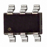
IC OP AMP HS VF 300MHZ SOT-23-6

EL5106IW-T7A

Manufacturer Part Number
EL5106IW-T7A
Description
IC OP AMP HS VF 300MHZ SOT-23-6
Manufacturer
Intersil
Datasheet

Specifications of EL5106IW-T7A

Amplifier Type
General Purpose
Number Of Circuits
1
Slew Rate
4500 V/µs
-3db Bandwidth
380MHz
Current - Input Bias
1.5µA
Voltage - Input Offset
1000µV
Current - Supply
1.5mA
Current - Output / Channel
100mA
Voltage - Supply, Single/dual (±)
5 V ~ 12 V, ±2.5 V ~ 6 V
Operating Temperature
-40°C ~ 85°C
Mounting Type
Surface Mount
Package / Case
SOT-23-6
Lead Free Status / RoHS Status
Contains lead / RoHS non-compliant
Output Type
-
Gain Bandwidth Product
-
350MHz Fixed Gain Amplifiers with Enable
The EL5106 and EL5306 are fixed gain amplifiers with a
bandwidth of 350MHz. This makes these amplifiers ideal for
today’s high speed video and monitor applications. They
feature internal gain setting resistors and can be configured
in a gain of +1, -1 or +2.
With a supply current of just 1.5mA and the ability to run
from a single supply voltage from 5V to 12V, these amplifiers
are also ideal for handheld, portable or battery powered
equipment.
The EL5106 and EL5306 also incorporate an enable and
disable function to reduce the supply current to 25µA typical
per amplifier. Allowing the CE pin to float or applying a low
logic level will enable the amplifier.
The EL5106 is offered in the 6 Ld SOT-23 and the
industry-standard 8 Ld SOIC packages and the EL5306 is
available in the 16 Ld SOIC and 16 Ld QSOP packages. All
operate over the industrial temperature range of -40°C to
+85°C.
Ordering Information
EL5106IWZ-T7* (Note 1)
EL5106IWZ-T7A* (Note 1)
EL5106IS
EL5106ISZ (Note 1)
EL5106ISZ-T7* (Note 1)
EL5106ISZ-T13* (Note 1)
EL5306ISZ (Note 1)
EL5306ISZ-T7* (Note 1)
EL5306ISZ-T13* (Note 1)
EL5306IUZ (Note 1)
EL5306IUZ-T7* (Note 1)
EL5306IUZ-T13* (Note 1)
*Please refer to TB347 for details on reel specifications.
NOTES:
1. These Intersil Pb-free plastic packaged products employ special Pb-free material sets, molding compounds/die attach materials, and 100%
2. The part marking is located on the bottom of the part.
matte tin plate plus anneal (e3 termination finish, which is RoHS compliant and compatible with both SnPb and Pb-free soldering operations).
Intersil Pb-free products are MSL classified at Pb-free peak reflow temperatures that meet or exceed the Pb-free requirements of IPC/JEDEC
J STD-020.
PART NUMBER
®
1
Data Sheet
BAFA (Note 2)
BAFA (Note 2)
5106IS
5106ISZ
5106ISZ
5106ISZ
EL5306ISZ
EL5306ISZ
EL5306ISZ
5306IUZ
5306IUZ
5306IUZ
PART MARKING
1-888-INTERSIL or 1-888-468-3774
CAUTION: These devices are sensitive to electrostatic discharge; follow proper IC Handling Procedures.
Features
• Pb-free available (RoHS compliant)
• Gain selectable (+1, -1, +2)
• 350MHz -3dB BW (A
• 1.5mA supply current per amplifier
• Fast enable/disable
• Single and dual supply operation, from 5V to 12V
• Available in SOT-23 packages
• 450MHz, 3.5mA product available (EL5108 and EL5308)
Applications
• Battery powered equipment
• Handheld, portable devices
• Video amplifiers
• Cable drivers
• RGB amplifiers
September 21, 2010
6 Ld SOT-23 (Pb-free)
8 Ld SOIC (150 mil)
8 Ld SOIC (150 mil) (Pb-free)
16 Ld SOIC (150 mil) (Pb-free)
16 Ld QSOP (150 mil) (Pb-free)
Copyright © Intersil Americas Inc. 2002-2005, 2007, 2010. All Rights Reserved.
All other trademarks mentioned are the property of their respective owners.
|
Intersil (and design) is a registered trademark of Intersil Americas Inc.
PACKAGE
V
= 2)
EL5106, EL5306
P6.064A
P6.064A
M8.15E
M8.15E
M8.15E
M8.15E
M8.15E
M8.15E
M8.15E
MDP0040
MDP0040
MDP0040
PKG. DWG. #
FN7357.6

Related parts for EL5106IW-T7A

EL5106IW-T7A Summary of contents

Page 1

... Ld SOIC packages and the EL5306 is available in the 16 Ld SOIC and 16 Ld QSOP packages. All operate over the industrial temperature range of -40°C to +85°C. Ordering Information PART NUMBER EL5106IWZ-T7* (Note 1) EL5106IWZ-T7A* (Note 1) EL5106IS EL5106ISZ (Note 1) EL5106ISZ-T7* (Note 1) EL5106ISZ-T13* (Note 1) EL5306ISZ (Note 1) EL5306ISZ-T7* (Note 1) ...

Page 2

Pinouts EL5106 (8 LD SOIC) TOP VIEW IN+ 3 VS- 4 EL5106 (6 LD SOT-23) TOP VIEW OUT EL5106, EL5306 CE 8 VS+ 7 OUT 6 ...

Page 3

... EL5106, EL5306 Thermal Information = +25°C) Storage Temperature . . . . . . . . . . . . . . . . . . . . . . . .-65°C to +150°C - -0. +0.5V Ambient Operating Temperature . . . . . . . . . . . . . . . .-40°C to +85° Operating Junction Temperature . . . . . . . . . . . . . . . . . . . . . . +125°C Power Dissipation . . . . . . . . . . . . . . . . . . . . . . . . . . . . . See Curves Pb-free Reflow Profile . . . . . . . . . . . . . . . . . . . . . . . . .see link below http://www.intersil.com/pbfree/Pb-FreeReflow.asp = -5V 150Ω +25°C Unless Otherwise Specified CONDITIONS ...

Page 4

Electrical Specifications +5V PARAMETER DESCRIPTION ENABLE t Enable Time EN t Disable Time DIS I CE Pin Input High Current IHCE I CE Pin Input Low Current ILCE V CE Input High Voltage for Power-down ...

Page 5

Typical Performance Curves ± 150Ω 100k 1M 10M FREQUENCY (Hz) FIGURE 1. FREQUENCY RESPONSE 1 150Ω L 1.2 0.8 0 FREQUENCY (Hz) FIGURE ...

Page 6

Typical Performance Curves 100 10 1 0.1 10k 100k 1M FREQUENCY (Hz) FIGURE 7. OUTPUT IMPEDANCE vs FREQUENCY ± 150Ω OP-P -30 -40 HD3 ...

Page 7

Typical Performance Curves FIGURE 13. PACKAGE POWER DISSIPATION vs AMBIENT TEMPERATURE Applications Information Product Description The EL5106 and EL5306 are fixed gain amplifier that offers a wide -3dB bandwidth of 350MHz and a low supply current of 1.5mA. They work ...

Page 8

IN- - IN+ + FIGURE 15 325Ω IN- 325Ω IN+ FIGURE 16 Supply Voltage Range and Single-Supply Operation The EL5106 and EL5306 have been designed to operate with ...

Page 9

... Load resistance L CHANGE Removed obsolete, leaded devices EL5106IW-T7, EL5106IW-T7A; EL5106IS-T7, EL5106IS- T13; EL5306IS, EL5306IS-T7, EL5306IS-T13; EL5306IU, EL5306IU-T7, EL5306IU-T13 Corrected Figure references in “Gain Setting” on page 7 (Fig 14 callout was referencing Fig 13; Fig 15 callout was referencing Fig 14; Fig 16 callout was referencing Fig 15) . ...

Page 10

Package Outline Drawing M8.15E 8 LEAD NARROW BODY SMALL OUTLINE PLASTIC PACKAGE Rev 0, 08/09 4 4.90 ± 0.10 PIN NO.1 ID MARK 5 1.27 TOP VIEW 1.75 MAX 0.175 ± 0.075 SIDE VIEW “A (1.27) (5.40) TYPICAL RECOMMENDED LAND ...

Page 11

Package Outline Drawing P6.064A 6 LEAD SMALL OUTLINE TRANSISTOR PLASTIC PACKAGE Rev 0, 2/10 1.90 0. PIN 1 INDEX AREA 0. TOP VIEW 5 2.90 SIDE VIEW (2.40) (0.95) ...

Page 12

... Accordingly, the reader is cautioned to verify that data sheets are current before placing orders. Information furnished by Intersil is believed to be accurate and reliable. However, no responsibility is assumed by Intersil or its subsidiaries for its use; nor for any infringements of patents or other rights of third parties which may result from its use ...

Related keywords