EL5223CL-T13 Intersil, EL5223CL-T13 Datasheet - Page 16
EL5223CL-T13
Manufacturer Part Number
EL5223CL-T13
Description
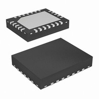
IC OPAMP 10-CH R-R 12MHZ 24-QFN
Manufacturer
Intersil
Datasheet
1.EL5423CLZ.pdf
(17 pages)
Specifications of EL5223CL-T13
Amplifier Type
Buffer
Number Of Circuits
8
Output Type
Rail-to-Rail
Slew Rate
18 V/µs
-3db Bandwidth
12MHz
Current - Input Bias
2nA
Voltage - Input Offset
500µV
Current - Supply
5.7mA
Current - Output / Channel
200mA
Voltage - Supply, Single/dual (±)
4.5 V ~ 16.5 V, ±2.25 V ~ 8.25 V
Operating Temperature
-40°C ~ 85°C
Mounting Type
Surface Mount
Package / Case
24-VQFN Exposed Pad, 24-HVQFN, 24-SQFN, 24-DHVQFN
Lead Free Status / RoHS Status
Contains lead / RoHS non-compliant
Gain Bandwidth Product
-


Thin Shrink Small Outline Plastic Packages (TSSOP)
NOTES:
10. Controlling dimension: MILLIMETER. Converted inch dimensions
N
1
1. These package dimensions are within allowable dimensions of
2. Dimensioning and tolerancing per ANSI Y14.5M-1982.
3. Dimension “D” does not include mold flash, protrusions or gate burrs.
4. Dimension “E1” does not include interlead flash or protrusions. Inter-
5. The chamfer on the body is optional. If it is not present, a visual index
6. “L” is the length of terminal for soldering to a substrate.
7. “N” is the number of terminal positions.
8. Terminal numbers are shown for reference only.
9. Dimension “b” does not include dambar protrusion. Allowable dambar
0.10(0.004)
JEDEC MO-153-AC, Issue E.
Mold flash, protrusion and gate burrs shall not exceed 0.15mm
(0.006 inch) per side.
lead flash and protrusions shall not exceed 0.15mm (0.006 inch) per
side.
feature must be located within the crosshatched area.
protrusion shall be 0.08mm (0.003 inch) total in excess of “b” dimen-
sion at maximum material condition. Minimum space between protru-
sion and adjacent lead is 0.07mm (0.0027 inch).
are not necessarily exact. (Angles in degrees)
2
-A-
INDEX
AREA
3
e
0.05(0.002)
b
D
M
C A
SEATING PLANE
M
E1
-C-
-B-
B S
A
16
E
A1
α
0.10(0.004)
0.25(0.010)
EL5123, EL5223, EL5323, EL5423
GAUGE
PLANE
0.010
A2
M
0.25
B
M
L
c
M20.173
20 LEAD THIN SHRINK SMALL OUTLINE PLASTIC
PACKAGE
SYMBOL
A1
A2
E1
A
D
E
N
α
b
c
e
L
0.002
0.031
0.0075
0.0035
0.252
0.169
0.246
0.0177
MIN
0
-
0.026 BSC
o
INCHES
20
0.047
0.006
0.051
0.0118
0.0079
0.260
0.177
0.256
0.0295
MAX
8
o
MILLIMETERS
0.05
0.80
0.19
0.09
6.40
4.30
6.25
0.45
MIN
0
-
o
0.65 BSC
20
MAX
1.20
0.15
1.05
0.30
0.20
6.60
4.50
6.50
0.75
8
o
August 31, 2010
Rev. 1 6/98
NOTES
FN7176.3
9
3
4
6
7
-
-
-
-
-
-
-
Related parts for EL5223CL-T13
Image
Part Number
Description
Manufacturer
Datasheet
Request
R

Part Number:
Description:
IC OPAMP 10-CH R-R 12MHZ 24-QFN
Manufacturer:
Intersil
Datasheet:
Part Number:
Description:
IC OPAMP 10-CH R-R 12MHZ 24-QFN
Manufacturer:
Intersil
Datasheet:

Part Number:
Description:
Intersil Corporation [CMOS Serial Controller Interface]
Manufacturer:
Intersil Corporation
Datasheet:
Part Number:
Description:
Manufacturer:
Intersil Corporation
Datasheet:
Part Number:
Description:
357-036-542-201 CARDEDGE 36POS DL .156 BLK LOPRO
Manufacturer:
Intersil Corporation
Datasheet:
Part Number:
Description:
1024-Word x 4-Bit LSI Static RAM
Manufacturer:
Intersil Corporation
Datasheet:
Part Number:
Description:
General Purpose NPN Transistor Arrays FN341.4
Manufacturer:
Intersil Corporation
Datasheet:
Part Number:
Description:
CMOS 16-Bit Microprocessor
Manufacturer:
Intersil Corporation
Datasheet:
Part Number:
Description:
Manufacturer:
Intersil Corporation
Datasheet:
Part Number:
Description:
Manufacturer:
Intersil Corporation
Datasheet:
Part Number:
Description:
Manufacturer:
Intersil Corporation
Datasheet:
Part Number:
Description:
Manufacturer:
Intersil Corporation
Datasheet:
Part Number:
Description:
CMOS 6-Bit Latch and Decoder Memory Interfaces
Manufacturer:
Intersil Corporation
Datasheet:
Part Number:
Description:
CA3046General Purpose NPN Transistor Arrays
Manufacturer:
Intersil Corporation
Datasheet:
Part Number:
Description:
Manufacturer:
Intersil Corporation
Datasheet: