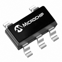
MCP1321T-29LE/OT Microchip Technology, MCP1321T-29LE/OT Datasheet - Page 22

MCP1321T-29LE/OT
Manufacturer Part Number
MCP1321T-29LE/OT
Description
IC SUPERVISOR 2.9V OD/PP SOT23-5
Manufacturer
Microchip Technology
Type
Simple Reset/Power-On Resetr
Specifications of MCP1321T-29LE/OT
Number Of Voltages Monitored
1
Package / Case
SOT-23-5, SC-74A, SOT-25
Output
Open Drain, Push-Pull
Reset
Active High/Active Low
Reset Timeout
140 ms Minimum
Voltage - Threshold
2.9V
Operating Temperature
-40°C ~ 125°C
Mounting Type
Surface Mount
Chip Enable Signals
No
Minimum Operating Temperature
- 40 C
Output Type
Active High or Active Low or Open Drain or Push-Pull
Power Fail Detection
No
Monitored Voltage
2 V to 4.7 V
Undervoltage Threshold
2.857 V
Overvoltage Threshold
2.944 V
Manual Reset
Resettable
Watchdog
Yes
Battery Backup Switching
No
Power-up Reset Delay (typ)
2240 ms
Supply Voltage (max)
5.5 V
Supply Voltage (min)
1 V
Supply Current (typ)
10 uA
Maximum Power Dissipation
240 mW
Mounting Style
SMD/SMT
Maximum Operating Temperature
+ 125 C
Input Voltage
5.5V
No. Of Outputs
1
Power Dissipation Pd
240mW
Supply Voltage Range
1V To 5.5V
No. Of Pins
5
Operating Temperature Range
-40°C To +125°C
Filter Terminals
SMD
Supply Voltage Min
1V
Rohs Compliant
Yes
Lead Free Status / RoHS Status
Lead free / RoHS Compliant
Lead Free Status / RoHS Status
Lead free / RoHS Compliant, Lead free / RoHS Compliant
Other names
MCP1321T-29LE/OT
MCP1321T-29LE/OTTR
MCP1321T-29LE/OTTR
Available stocks
Company
Part Number
Manufacturer
Quantity
Price
Company:
Part Number:
MCP1321T-29LE/OT
Manufacturer:
MICROCHIP
Quantity:
12 000
MCP131X/2X
3.1
V
input voltage. Typically, the circuit ground is used.
3.2
V
voltage level that requires monitoring.
3.3
There are four types of Reset output pins. These are:
1.
2.
3.
4.
Some devices have both an active-low and active-high
Reset output.
3.3.1
The RST open-drain output remains low while V
below the Reset voltage threshold (V
device voltage (V
V
delay timer (T
will float, and an external pull-up resistor is required to
bring the output to the high state.
3.3.2
The RST open-drain output remains low while V
below the Reset voltage threshold (V
device voltage (V
V
delay timer (T
will be pulled high by an internal pull-up resistor (typi-
cally 4.7 kΩ).
3.3.3
The RST push-pull output remains low while V
below the Reset voltage threshold (V
device voltage (V
V
delay timer (T
will be driven to the high state.
3.3.4
The RST push-pull output remains high while V
below the Reset voltage threshold (V
device voltage (V
V
delay timer (T
will be driven to the low state.
DS21985B-page 22
SS
DD
HYS
HYS
HYS
HYS
Open-Drain active-low Reset, External pull-up
resistor required
Open-Drain active-low Reset, Internal pull-up
resistor
Push-Pull active-low Reset
Push-Pull active-high Reset
provides the negative reference for the analog
can be used for power supply monitoring or a
), the device will remain in Reset for the Reset
), the device will remain in Reset for the Reset
), the device will remain in Reset for the Reset
), the device will remain in Reset for the Reset
Ground Terminal (V
Supply Voltage (V
Reset Output (RST and RST)
ACTIVE-LOW (RST) - OPEN-DRAIN,
EXTERNAL PULL-UP RESISTOR
ACTIVE-LOW (RST) - OPEN-DRAIN,
INTERNAL PULL-UP RESISTOR
ACTIVE-LOW (RST) - PUSH-PULL
ACTIVE-HIGH (RST) - PUSH-PULL
RST
RST
RST
RST
). After that time expires, the RST pin
). After that time expires, the RST pin
). After that time expires, the RST pin
). After that time expires, the RST pin
DD
DD
DD
DD
) returns to a high level (V
) returns to a high level (V
) returns to a high level (V
) returns to a high level (V
DD
SS
)
)
TRIP
TRIP
TRIP
TRIP
). Once the
). Once the
). Once the
). Once the
TRIP
TRIP
TRIP
TRIP
DD
DD
DD
DD
is
is
is
is
+
+
+
+
3.4
The Manual Reset (MR) input pin allows a push button
switch to easily be connected to the system. When the
push button is depressed, it forces a system Reset.
This pin has circuitry that filters noise that may be
present on the MR signal.
The MR pin is active-low and has an internal pull-up
resistor.
3.5
In some systems, it is desirable to have an external
Watchdog Timer to monitor the operation of the sys-
tem. This is done by requiring the embedded controller
to “pet” the Watchdog Timer within a predetermined
time frame (T
within this time frame, the MCP131X/2X will force the
Reset pin(s) active.
The embedded controller “pets” the MCP131X/2X by
forcing an edge transition on the WDI pin. The WDT
Timer is activated by the first falling edge on the WDI
pin.
The standard offering devices have a typical Watchdog
Timer period (T
able Watchdog Timer periods.
Manual Reset Input (MR)
Watchdog Input
WD
WD
). If the MCP131X/2X is not “petted”
) of 1.6 s.
© 2007 Microchip Technology Inc.
Table 1-3
shows the avail-


