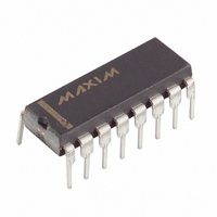
DS1831 Maxim Integrated Products, DS1831 Datasheet

DS1831
Specifications of DS1831
Available stocks
Related parts for DS1831
DS1831 Summary of contents
Page 1
... SO DESCRIPTION The DS1831 multisupply monitor and reset monitors up to four system voltages: 5V supply, 3.3V (or 3V) supply, and two additional user configurable voltage monitors. DS1831 power for internal operation comes from the higher voltage level of the 3.3V input or the 5V input. One of these inputs must be greater than 1V for device operation ...
Page 2
... The DS1831A replaces one reference comparator and the master pushbutton with watchdog and the DS1831B replaces the 3.3V last reset status output. TOL and TD inputs allow user configuration of the DS1831 for multiple applications. The TOL inputs configure the tolerance for the specified output and the TD inputs configure the reset time delays ...
Page 3
... The DS1831 provides two TD inputs for individual customization of reset time-delays and an additional one for the DS1831A watchdog. TD inputs select time delays for the IN the Watchdog on the DS1831A. The reset time delays are shown in Table 1. These allow the selection of minimum delays of 10ms, 100ms, and 1000ms. ...
Page 4
... OPERATION—PUSHBUTTON RESET The DS1831 provides three pushbutton inputs for manual reset of the device. Pushbutton inputs for the 3.3V reset, 5V reset, and a master pushbutton reset (DS1831 and DS1831B only) input; provide multiple options for system control. The 3.3V pushbutton reset and 5V pushbutton resets provide a simple manual reset for the associated reset output ...
Page 5
... PUSHBUTTON RESET Figure 3 TIMING DIAGRAM—MASTER PUSHBUTTON RESET Figure 4 MPBRST t PDLY V IL RST and RST 5V 3.3V NMI1 and NMI2 5V Supply RST 5V 2 DS1831 TOL PBRST 5V 5 GND RST t NMI ...
Page 6
... OPERATION—PUSHBUTTON STATUS The DS1831B provides a master pushbutton status open drain output. The status of the most recent reset condition. If the last reset was generated by the master pushbutton input it would maintain a low condition until cleared by another event (except the master pushbutton) generating a reset ...
Page 7
... The DS1831 requires pull-up resistors on the outputs to maintain a valid output. The value of the pull up resistor is not critical in most cases but must be set low enough to pull the output to a high state. A common pull-up resistor value used is 10kW (see Figure 7). APPLICATION DIAGRAM— ...
Page 8
The output associated with the specific input will be held low if the voltage on the input pin is less than 1.25V. If the voltage is above 1.25V the output will not sink current and will be pulled up by ...
Page 9
... Resulting In 820kW Repeat the same steps to solve for R3 and R4 with V OPERATION - WATCHDOG TIMER The watchdog timer function (DS1831A only) forces the does not have a transition (high-to-low or low-to-high) within the predetermined time period. The time- out period is determined by the condition of the TD the minimum watchdog time-out would be 10ms, TD floating would yield a minimum time-out of 100ms, ...
Page 10
... Table 1. A typical circuit example is shown in Figure 10. The watchdog timing is shown in Figure 11. The DS1831A watchdog function cannot be disabled. The watchdog strobe input must be strobed to avoid a watchdog time-out however the watchdog status output can be disconnected yielding the same result. WATCHDOG CIRCUIT EXAMPLE Figure 10 ...
Page 11
RESET TIMING DIAGRAM—POWER UP Figure 3.3V RST (or RST 5V RESET TIMING DIAGRAM — POWER DOWN Figure 3.3V V INTP RST (or RST 5V V (MAX) INTP V INTP ...
Page 12
ABSOLUTE MAXIMUM RATINGS* Voltage 3.3V Pins Relative to Ground Voltage on either RST Relative to Ground Voltage on PBRST Relative to Ground 3.3V Voltage on PBRST Relative to Ground 5V Voltage on MPBRST, IN1, IN2 ...
Page 13
CAPACITANCE PARAMETER SYMBOL Input Capacitance Input Capacitance AC ELECTRICAL CHARACTERISTICS PARAMETER RESET Active Time (TD=Low) RESET Active Time (TD=Float) RESET Active Time (TD=High) V Detect to RST CC V Detect to RST CC VIN Detect to NMI NMI Active Time ...
Page 14
... DS1831 16-Pin DIP 300mil DS1831S 16-Pin SO 150mil DS1831A 16-Pin DIP 300mil DS1831AS 16-Pin SO 150mil DS1831B 16-Pin DIP 300mil DS1831BS 16-Pin SO 150mil * Add “/T&R” for tape and reeling of surface mount packages. Description 5V/3.3V Multisupply Monitor 5V/3.3V Multisupply Monitor 5V/3.3V Multisupply Monitor w/Watchdog 5V/3 ...


