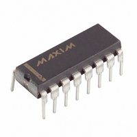
DS1831 Maxim Integrated Products, DS1831 Datasheet - Page 4

DS1831
Manufacturer Part Number
DS1831
Description
IC MULTIMON 5V/3.3V 16-DIP
Manufacturer
Maxim Integrated Products
Series
MicroMonitor™r
Type
Multi-Voltage Supervisorr
Datasheet
1.DS1831S.pdf
(14 pages)
Specifications of DS1831
Number Of Voltages Monitored
4
Output
Open Drain or Open Collector
Reset
Active Low
Reset Timeout
10 ms; 100 ms; 1,000 ms Minimum
Voltage - Threshold
3.3V, 5V, Adj, Adj
Operating Temperature
-40°C ~ 85°C
Mounting Type
Through Hole
Package / Case
16-DIP (0.300", 7.62mm)
Lead Free Status / RoHS Status
Contains lead / RoHS non-compliant
Available stocks
Company
Part Number
Manufacturer
Quantity
Price
Part Number:
DS1831AS
Manufacturer:
DALLAS
Quantity:
20 000
Part Number:
DS1831C
Manufacturer:
DALLAS
Quantity:
20 000
Company:
Part Number:
DS1831CS+
Manufacturer:
Maxim Integrated Products
Quantity:
135
Part Number:
DS1831CS+
Manufacturer:
MAXIM/美信
Quantity:
20 000
Company:
Part Number:
DS1831DS
Manufacturer:
DALLAS
Quantity:
2
Part Number:
DS1831S
Manufacturer:
MAXIM/美信
Quantity:
20 000
PUSHBUTTON RESET SEQUENCING Figure 2
NOTE: The
therefore does not require a pull-up resistor (an addition pull up can be used to accelerate responses). If an
external pull up is used in this example it must be connected to the 3.3V power supply.
OPERATION—PUSHBUTTON RESET
The DS1831 provides three pushbutton inputs for manual reset of the device. Pushbutton inputs for the
3.3V reset, 5V reset, and a master pushbutton reset (DS1831 and DS1831B only) input; provide multiple
options for system control. The 3.3V pushbutton reset and 5V pushbutton resets provide a simple manual
reset for the associated reset output; while the master pushbutton reset forces all resets and NMI outputs
active low.
The 5V reset pushbutton input and the 3.3V reset pushbutton input provide manual reset control input for
each associated reset output. When the output associated with a pushbutton input is not active, a
pushbutton reset can be generated by pulling the associated
pushbutton is held low the reset will be forced active and will remain active for a reset cycle after the
pushbutton is released. See Figure 2 for an application example that allows a user to sequence the reset
outputs.
A master pushbutton reset cycle can be started if at least one voltage input (IN
tolerance and at least one output is active. A master pushbutton reset is generated by pulling the
pin low for at least 20µs. When the pushbutton is held low all outputs are forced active and will remain
active for a reset or NMI time delay after the pushbutton is released. The Master Pushbutton input is
pulled high through an internal 100kW pull up resistor and debounced via internal circuitry. See Figure 3
for an application example. Figures 4 and 5 for the timing diagram.
The 5V and 3.3V pushbutton reset inputs are pulled high through an internal 100kW pull up resistor to the
voltage input, which is associated with that pushbutton. The master pushbutton is pulled to the greater of
the IN
5V
and IN
RST
3.3V
5V
inputs.
output is connected to the IN
GND
5V Supply
PBRST
RST
TOL
TD
IN
5V
5V
5V
5V
5V
3.3V
1
2
3
4
5
4 of 14
DS1831
via a 100 kW resistor in the push-button input and
16
15
14
13
12
PBRST
TD
TOL
RST
PBRST
IN
3.3V
3.3V
3.3V
3.3V
pin low for at least 20µs. When the
3.3V
3.3V Supply
5V
, IN
3.3V
, IN1, or IN2) is in
MPBRST


