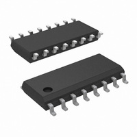
LP2953AIM/NOPB National Semiconductor, LP2953AIM/NOPB Datasheet - Page 13

LP2953AIM/NOPB
Manufacturer Part Number
LP2953AIM/NOPB
Description
IC REG LDO ADJ 250MA 16-SOIC
Manufacturer
National Semiconductor
Datasheet
1.LP2953IMNOPB.pdf
(22 pages)
Specifications of LP2953AIM/NOPB
Regulator Topology
Positive Adjustable
Voltage - Output
1.23 ~ 29 V
Voltage - Input
Up to 30V
Voltage - Dropout (typical)
0.47V @ 250mA
Number Of Regulators
1
Current - Output
250mA
Operating Temperature
-40°C ~ 125°C
Mounting Type
Surface Mount
Package / Case
16-SOIC (3.9mm Width)
Lead Free Status / RoHS Status
Lead free / RoHS Compliant
Current - Limit (min)
-
Other names
*LP2953AIM
*LP2953AIM/NOPB
LP2953AIM
*LP2953AIM/NOPB
LP2953AIM
Application Hints
The next parameter which must be calculated is the maxi-
mum allowable temperature rise, T
by using the formula:
where: T
Using the calculated values for T
required value for junction-to-ambient thermal resistance,
θ
The heatsink is made using the PC board copper. The heat
is conducted from the die, through the lead frame (inside the
part), and out the pins which are soldered to the PC board.
The pins used for heat conduction are given in Table 1.
Figure 2 shows copper patterns which may be used to
dissipate heat from the LP2952 and LP2953. Table 2 shows
some values of junction-to-ambient thermal resistance (θ
for values of L and W for 1 oz. copper.
LP2952IN, LP2952AIN,
LP2952IN-3.3,
LP2952AIN-3.3
LP2953IN, LP2953AIN,
LP2953IN-3.3,
LP2953AIN-3.3
LP2952IM, LP2952AIM,
LP2952IM-3.3,
LP2952AIM-3.3,
LP2953IM, LP2953AIM,
LP2953IM-3.3,
LP2953AIM-3.3
(J–A)
T
R
(max) = T
, can now be found:
FIGURE 1. P
temperature
T
J
A
(max)
(max) is the maximum ambient temperature
Part
TABLE 1. Heat Conducting Pins
J
(max) − T
Current/Voltage Diagram
is
TOTAL
the
A
= (V
(max)θ
maximum
16-Pin Surface
IN
14-Pin DIP
16-Pin DIP
(Continued)
Package
− V
Mount
(J–A)
R
R
(max). This is calculated
(max) and P(max), the
OUT
= T
) I
allowable
L
R
01112707
(max)/P(max)
+ (V
4, 5, 12, 13
1, 8, 9, 16
10, 11, 12
IN
3, 4, 5,
Pins
) I
junction
G
J–A
)
13
* For best results, use L = 2H
** 14-Pin DIP is similar, refer to Table 1 for pins designated for
heatsinking.
HEATSINK REQUIREMENTS (Military Temperature
Range Devices)
The
LP2953AMJ is limited by the maximum junction temperature
(+150˚C) and the two parameters that determine how quickly
heat flows away from the die: the ambient temperature and
the junction-to-ambient thermal resistance of the part.
16-Pin DIP
14-Pin DIP
Surface Mount
TABLE 2. Thermal Resistance for Various Copper
Package
maximum
FIGURE 2. Copper Heatsink Patterns
allowable
Heatsink Patterns
L (in.)
1
2
3
4
6
1
2
3
1
2
3
6
4
2
power
H (in.)
0.19
0.19
0.19
0.19
0.19
0.5
1.5
0.5
1.5
0.5
1.5
1
1
1
dissipation
θ
01112708
J–A
www.national.com
70
60
58
66
66
65
51
49
83
70
67
69
71
73
(˚C/W)
for
the


