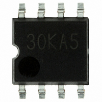
BD30KA5WF-E2 Rohm Semiconductor, BD30KA5WF-E2 Datasheet - Page 4

BD30KA5WF-E2
Manufacturer Part Number
BD30KA5WF-E2
Description
IC REG LDO 500MA 3.0V SHTDN SOP8
Manufacturer
Rohm Semiconductor
Datasheet
1.BD10KA5WFP-E2.pdf
(10 pages)
Specifications of BD30KA5WF-E2
Regulator Topology
Positive Fixed
Voltage - Output
3V
Voltage - Input
Up to 5.5V
Voltage - Dropout (typical)
0.12V @ 200mA
Number Of Regulators
1
Current - Output
500mA (Max)
Operating Temperature
-40°C ~ 105°C
Mounting Type
Surface Mount
Package / Case
8-SOP
Number Of Outputs
1
Polarity
Positive
Input Voltage Max
5.5 V
Output Voltage
3 V
Output Type
Fixed
Dropout Voltage (max)
0.2 V at 200 mA
Output Current
500 mA
Line Regulation
35 mV
Load Regulation
75 mV
Voltage Regulation Accuracy
1 %
Maximum Power Dissipation
0.6876 W
Maximum Operating Temperature
+ 105 C
Mounting Style
SMD/SMT
Minimum Operating Temperature
- 40 C
Lead Free Status / RoHS Status
Lead free / RoHS Compliant
Current - Limit (min)
-
Lead Free Status / Rohs Status
Lead free / RoHS Compliant
Other names
BD30KA5WF-E2TR
●Block diagrams, Standard circuit examples
© 2009 ROHM Co., Ltd. All rights reserved.
BD□□KA5,BD□□KA5W Series,BD00KA5W Series
[BD00KA5WFP]
www.rohm.com
[BD□□KA5WFP]
TO252-5(BD00KA5WFP)
TO252-5(BD□□KA5WFP)
TO252-5(BD□□KA5FP)
Pin No.
Pin No.
Pin No.
FIN
CTL (1PIN)
FIN
CTL (1PIN)
FIN
1
2
3
1
2
3
4
5
1
2
3
4
5
Vcc (1PIN)
Vcc (2PIN)
Vcc (2PIN)
Pin Name
Vref
Pin Name
PinName
Vref
Vref
GND
N.C.
OUT
GND
OUT
GND
Vcc
N.C.
OUT
CTL
N.C.
N.C.
CTL
ADJ
Vcc
Vcc
TSD
TSD
TSD
1μF
1μF
1μF
N.C.(3PIN)
N.C.(3PIN)
N.C.(2PIN)
Fig.13
Fig.14
Fig.15
Output voltage configuration terminal
Output voltage ON/OFF control
Output voltage ON/OFF control
1μF
1μF
1μF
Power supply voltage input
OUT (4PIN)
Power supply voltage input
OUT (3PIN)
Power supply voltage input
OUT (4PIN)
Driver
Driver
Driver
Unconnected terminal
Unconnected terminal
Unconnected terminal
Unconnected terminal
GND(FIN)
GND(FIN)
Voltage output
Voltage output
OCP
OCP
Voltage output
OCP
Function
R2
Function
Function
GND
N.C.(5PIN)
GND
GND
R2
R2
R1
R1
ADJ(5PIN)
R1
VOUT=VADJ×(R1+R2)÷R1(V)
:VADJ=0.75V(Typ.)
:A value of approximately 30kΩ
is recommended for R1.
*Output voltage configuration
1
1
1
TOP VIEW
TOP VIEW
TO252-5
TOP VIEW
TO252-5
2
2
TO252-3
FIN
FIN
FIN
2
3
3
4 5
4 5
3
4/9
[BD00KA5WF]
[BD□□KA5WF]
SOP8(BD00KA5WF)
Vcc(8PIN)
Vcc(8PIN)
SOP8(BD□□KA5WF)
N.C. pins are electrically open to the inside of the IC chip.
Pin No.
Pin No.
1μF
1μF
1
2
3
4
5
6
7
8
1
2
3
4
5
6
7
8
1μF
OUT(1PIN)
1μF
OUT(1PIN)
R2
GND(7PIN)
GND(7PIN)
N.C.(3PIN)
Pin Name
Pin Name
Vref
Vref
ADJ(2PIN)
R1
GND
OUT
GND
OUT
N.C.
N.C.
CTL
ADJ
CTL
Vcc
Vcc
TSD
TSD
Fig.16
Fig.17
Output voltage configuration terminal
Output voltage ON/OFF control
Output voltage ON/OFF control
GND(6PIN)
GND(6PIN)
Power supply voltage input
Power supply voltage input
N.C.(3PIN) N.C.(4IN)
Driver
Driver
Unconnected terminal
Unconnected terminal
N.C.(3PIN) N.C.(4IN)
Voltage output
Voltage output
OCP
OCP
Function
Function
GND
GND
CTL (5PIN)
CTL (5PIN)
R2
R1
VOUT=VADJ×(R1+R2)÷R1(V)
:VADJ=0.75V(Typ.)
:A value of approximately 30kΩ
is recommended for R1.
*Output voltage configuration
Technical Note
2009.04 - Rev.A
TOP VIEW
TOP VIEW
8
8
1
1
SOP8
SOP8
5
4
5
4


