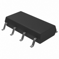
TISP61089BDR Bourns Inc., TISP61089BDR Datasheet - Page 8

TISP61089BDR
Manufacturer Part Number
TISP61089BDR
Description
SURGE SUPP SLIC PROG HV 8-SOP
Manufacturer
Bourns Inc.
Datasheet
1.TISP61089BDR-S.pdf
(20 pages)
Specifications of TISP61089BDR
Package / Case
8-SOIC (3.9mm Width)
Voltage - Breakover
*
Voltage - Off State
170V
Current - Peak Pulse (10 X 1000µs)
30A
Current - Hold (ih)
150mA
Number Of Elements
2
Capacitance
100pF
Applications
SLIC
Number Of Circuits
2
Voltage - Working
-100V
Voltage - Clamping
-112V
Technology
Mixed Technology
Breakover Current Ibo Max
6.5 A
Rated Repetitive Off-state Voltage Vdrm
170 V
Off-state Leakage Current @ Vdrm Idrm
0.005 mA
Holding Current (ih Max)
150 mA
Mounting Style
SMD/SMT
Power (watts)
-
Lead Free Status / RoHS Status
Lead free / RoHS Compliant
Available stocks
Company
Part Number
Manufacturer
Quantity
Price
Part Number:
TISP61089BDR
Manufacturer:
BOURNS/伯恩斯
Quantity:
20 000
Company:
Part Number:
TISP61089BDR-S
Manufacturer:
LITTLEFUSE
Quantity:
4 114
Company:
Part Number:
TISP61089BDR-S
Manufacturer:
Bourns Inc.
Quantity:
31 562
Part Number:
TISP61089BDR-S
Manufacturer:
BOURNS/伯恩斯
Quantity:
20 000
Specifications are subject to change without notice.
Customers should verify actual device performance in their specific applications.
SLICs have become more sophisticated. To minimize power consumption, some designs automatically adjust the driver supply voltage to a
value that is just sufficient to drive the required line current. For short lines, the supply voltage would be set low, but for long lines, a higher
supply voltage would be generated to drive sufficient line current. The optimum protection for this type of SLIC would be given by a protection
voltage which tracks the SLIC supply voltage. This can be achieved by connecting the protection thyristor gate to the SLIC V
Figure 6. This gated (programmable) protection arrangement minimizes the voltage stress on the SLIC, no matter what value of supply voltage.
Operation of Gated Protectors
Figure 7 and Figure 8 show how the TISP61089B limits negative and positive overvoltages. Positive overvoltages (Figure 8) are clipped by the
antiparallel diode of Th5 and the resulting current is diverted to ground. Negative overvoltages (Figure 7) are initially clipped close to the SLIC
negative supply rail value (V
condition. As the overvoltage subsides the high holding current of Th5 prevents d.c. latchup. The protection voltage will be the sum of the gate
supply (V
gate decoupling capacitor, C1, and the gate terminal. During the initial rise of a fast impulse, the gate current (I
current (I
OCTOBER 2000 - REVISED JULY 2008
Gated Protectors (Continued)
TISP61089B High Voltage Ringing SLIC Protector
K
BATH
Figure 7. Negative Overvoltage Condition
). Rates of 80 A/µs can cause inductive voltages of 0.8 V in 2.5 cm of printed wiring track. To minimize this inductive voltage increase of
) and the peak gate-cathode voltage (V
AI6XAHB
I
K
PROTECTOR
V
BATH
Figure 6. TISP61089B Buffered Gate Protector (‘1089 Section 4.5.12 Testing)
61089B
BATH
SLIC
TISP
0 - 600 V r.m.s.
GENERATOR
RESISTANCE
GENERATOR
Th5
SOURCE
). If sufficient current is available from the overvoltage, then Th5 will switch into a low voltage on-state
600 Ω Ω Ω Ω
600 Ω Ω Ω Ω
A.C.
I
G
220 nF
WIRE
WIRE
RING
TIP
C1
SLIC
40 Ω Ω Ω Ω
40 Ω Ω Ω Ω
R1
R2
GK(BO)
). The protection voltage will be increased if there is a long connection between the
TISP61089B
220 nF
C1
I
G
SLIC
Figure 8. Positive Overvoltage Condition
V
BATH
AI6XAIB
I
I
V
I
BATH
SLIC
F
BATL
SWITCHING MODE
POWER SUPPLY
PROTECTOR
C2
V
BATH
D1
61089B
SLIC
TISP
Tx
AI6XCC
G
Th5
) is the same as the cathode
220 nF
C1
SLIC
BATH
supply,


