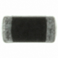
B72500D90A60 EPCOS Inc, B72500D90A60 Datasheet - Page 16

B72500D90A60
Manufacturer Part Number
B72500D90A60
Description
CERADIODE 9VDC 30A 0603
Manufacturer
EPCOS Inc
Series
CeraDioder
Datasheet
1.B72590D50A60.pdf
(22 pages)
Specifications of B72500D90A60
Package / Case
0603 (1608 Metric)
Varistor Voltage
10V
Current-surge
30A
Number Of Circuits
1
Maximum Dc Volts
9VDC
Polarity
Bidirectional
Clamping Voltage
30 V
Operating Voltage
9 V
Breakdown Voltage
10 V
Termination Style
SMD/SMT
Peak Surge Current
30 A
Peak Pulse Power Dissipation
1600 W
Capacitance
220 pF
Maximum Operating Temperature
+ 85 C
Minimum Operating Temperature
- 40 C
Mounting Style
SMD/SMT
Diode Type
ESD Protection
Clamping Voltage Vc Max
30V
Diode Case Style
0603
Operating Temperature Range
-40°C To +85°C
Operating Temperature Min Deg. C
-40C
Operating Temperature Max Deg. C
85C
Lead Free Status / RoHS Status
Lead free / RoHS Compliant
Energy
-
Maximum Ac Volts
-
Lead Free Status / Rohs Status
Lead free / RoHS Compliant
Other names
495-3415-2
B72500D 90A 60
B72500D0090A060
CDS3C09GTA
B72500D 90A 60
B72500D0090A060
CDS3C09GTA
Available stocks
Company
Part Number
Manufacturer
Quantity
Price
Company:
Part Number:
B72500D90A60
Manufacturer:
EPCOS Inc
Quantity:
41 675
Company:
Part Number:
B72500D90A60
Manufacturer:
TDK-EPCOS
Quantity:
84 000
5
5.1
5.2
Manual soldering with a soldering iron must be avoided, hot-air methods are recommended for
making repairs.
5.3
All environmentally compatible agents are suitable for cleaning. Select the appropriate cleaning
solution according to the type of flux used. The temperature difference between the components
and cleaning liquid must not be greater than 100 C. Ultrasonic cleaning should be carried out
with the utmost caution. Too high ultrasonic power can impair the adhesive strength of the metal-
lized surfaces. Insufficient or excessive cleaning can be detrimental to CeraDiode performance.
5.4
An excessive application of solder paste results in too high a solder fillet, thus making the chip
more susceptible to mechanical and thermal stress. This will lead to the formation of cracks. Too
little solder paste reduces the adhesive strength on the outer electrodes and thus weakens the
bonding to the PCB. The solder should be applied smoothly to the end surface to a height of
min. 0.2 mm.
5.5
Used flux should have less than or equal to 0.1 wt % of halogenated content, since flux residue
after soldering could lead to corrosion of the termination and/or increased leakage current on the
surface of the CeraDiode. Strong acidic flux must not be used. The amount of flux applied should
be carefully controlled, since an excess may generate flux gas, which in turn is detrimental to sol-
derability.
5.6
Solderability is guaranteed for one year from date of delivery, provided that components are
stored in their original packages.
Storage temperature:
Relative humidity:
The solderability of the external electrodes may deteriorate if SMDs are stored where they are ex-
posed to high humidity, dust or harmful gas (hydrogen chloride, sulfurous acid gas or hydrogen
sulfide).
Do not store SMDs where they are exposed to heat or direct sunlight. Otherwise the packing ma-
terial may be deformed or SMDs may stick together, causing problems during mounting.
After opening the factory seals, such as polyvinyl-sealed packages, it is recommended to use the
SMDs as soon as possible.
Please read Cautions and warnings and
Important notes at the end of this document.
CeraDiodes
Standard series
The average ramp-up rate must not exceed 3 C/s.
The cooling rate must not exceed 8 C/s.
Notes for proper soldering
Preheating and cooling
Repair / rework
Cleaning
Solder paste printing (reflow soldering)
Selection of flux
Storage
75% annual average, 95% on 30 days a year
25 C to +45 C
Page 16 of 22


