MT5600BA-V92-NAM Multi-Tech Systems, MT5600BA-V92-NAM Datasheet - Page 51
MT5600BA-V92-NAM
Manufacturer Part Number
MT5600BA-V92-NAM
Description
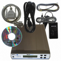
MODEM V.92 WORLD DATA/FAX LEASE
Manufacturer
Multi-Tech Systems
Series
MultiModem® IIr
Specifications of MT5600BA-V92-NAM
Data Format
V.92
Interface
RS-232
Voltage - Supply
9 V ~ 12 V
Mounting Type
Desktop
Package / Case
9.0" L x 6.2" W x 1.4" H (229mm x 158mm x 36mm)
Lead Free Status / RoHS Status
Lead free / RoHS Compliant
Other names
881-1018


RS-232 Pin Descriptions
Multi-Tech Systems, Inc. MT5600BA-V92 User Guide
Label
CGND
TD
RD
RTS
CTS
DSR
GND
CFLO
+12V
TCLK
RCLK
V54-2
DTR
RDL
RI
XCLK
TM
Appendix D - Pin Descriptions
Pin
1
2
3
4
5
7
8
9
10
11
12
13
14
15
16
17
18
19
20
21
22
23
24
25
6
I/O Type
GND
Out
GND
CD
TC
RC
AL
DTR
RDL
XCLK
TM
Signal Name/Description
CGND is tied common to GND on the modem’s PCB.
Transmitted Data The DTE uses the TD line to send data to the
modem for transmission over the telephone line or to transmit
commands to the modem.
Received Data The modem uses the RD line to send data received
from the telephone line to the DTE and to send modem responses to
the DTE.
Request to Send The RTS signal is used for hardware flow control.
Clear To Send CTS is controlled by the modem to indicate whether or
not the modem is ready to transmit data. CTS high indicates to the DTE that
signals presented on TD will be transmitted to the telephone line.
CTS low indicates to the DTE that it should not transfer data across
the interface on TD.
Data Set Ready DSR indicates modem status to the DTE. DSR low
indicates that the DTE is to disregard all signals appearing on the
interchange circuits except Ring Indicator (RI). It reflects the status of
the local data set, and does not indicate an actual link with any
remote data equipment.
Ground.
Carrier Detect The modem uses the CD line to signal to the DTE
that a carrier has been detected.
A positive voltage output from the modem used for tests or for
strapping signals high if needed.
NC
NC
NC
NC
NC
Transmit Clock Output from modem, used in synchronous mode.
NC
Receive Clock Output from modem, used in synchronous mode.
Analog Loop Input to modem to enable analog loop test.
NC
Data Terminal Ready Input to modem from DTE to control
answering and disconnection of modem.
Remote Digital Loop Input to modem to enable RDL test.
Ring Indicator RI output high indicates the presence of a ring signal
on the telephone line.
NC
External Clock Input to modem used in special synchronous
applications.
Test Mode Output from modem to indicate modem is in one of the
test modes.
Appendix D – Pin Descriptions
51
Related parts for MT5600BA-V92-NAM
Image
Part Number
Description
Manufacturer
Datasheet
Request
R

Part Number:
Description:
MODEM V.92 DATA/FAX WORLD
Manufacturer:
Multi-Tech Systems
Datasheet:
Part Number:
Description:
MODEM V.92 DATA/FAX WORLD
Manufacturer:
Multi-Tech Systems
Datasheet:
Part Number:
Description:
MODEM V.92 DATA/FAX WORLD
Manufacturer:
Multi-Tech Systems
Datasheet:
Part Number:
Description:
A Complete, Ready to Integrate Serial to Ethernet Module for IP Connectivity
Manufacturer:
Multi-Tech Systems

Part Number:
Description:
KIT DEV SOCKETMODEM PARALLEL
Manufacturer:
Multi-Tech Systems
Datasheet:

Part Number:
Description:
KIT DEV SRL SOCKETMODEM UNIVERSL
Manufacturer:
Multi-Tech Systems
Datasheet:

Part Number:
Description:
KIT DEV RJMODEM
Manufacturer:
Multi-Tech Systems
Datasheet:

Part Number:
Description:
Development Software EDGE Modem Developers Kit
Manufacturer:
Multi-Tech Systems
Datasheet:
Part Number:
Description:
Development Software EDGE Modem with GPS Only
Manufacturer:
Multi-Tech Systems
Datasheet:
Part Number:
Description:
Development Software EDGE Modem Only
Manufacturer:
Multi-Tech Systems
Datasheet:

Part Number:
Description:
MODEM V.34 SERIAL DATA 3.3V
Manufacturer:
Multi-Tech Systems
Datasheet:

Part Number:
Description:
MODEM V.32 SERIAL DATA/FAX 5V
Manufacturer:
Multi-Tech Systems
Datasheet:

Part Number:
Description:
MODEM V.32BIS SERIAL DATA/FAX 5V
Manufacturer:
Multi-Tech Systems
Datasheet:

Part Number:
Description:
MODEM RJ-11 V.92 SRL DATA 3.3V
Manufacturer:
Multi-Tech Systems
Datasheet:

Part Number:
Description:
MODEM V.92 SERIAL DATA/FAX 5V
Manufacturer:
Multi-Tech Systems
Datasheet: