NFR25H0004707JR500 Vishay, NFR25H0004707JR500 Datasheet - Page 3
NFR25H0004707JR500
Manufacturer Part Number
NFR25H0004707JR500
Description
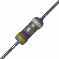
RES .47 OHM .50W 5% MF FUSIBLE
Manufacturer
Vishay
Series
NFR25Hr
Type
Metal Alloyr
Datasheet
1.NFR2500001008JR500.pdf
(10 pages)
Specifications of NFR25H0004707JR500
Resistance (ohms)
0.47
Power (watts)
0.5W, 1/2W
Composition
Metal Film
Features
Flame Proof, Fusible
Temperature Coefficient
±200ppm/°C
Tolerance
±5%
Size / Dimension
0.098" Dia x 0.295" L (2.50mm x 7.50mm)
Lead Style
Through Hole
Package / Case
Axial
Resistance In Ohms
0.47
Case
Axial
Power Rating(s)
1/2W
Resistance
470mOhm
Tolerance (+ Or -)
5%
Mounting Style
Through Hole
Construction
Axial
Case Style
Conformal
Military Standard
Not Required
Failure Rate
Not Required
Lead Spacing (nom)
Not Requiredmm
Product Length (mm)
7.5mm
Product Depth (mm)
Not Requiredmm
Product Height (mm)
Not Requiredmm
Resistance Tolerance
± 5%
Power Rating
500mW
Voltage Rating
350V
Resistor Element Material
Metal Film
Rohs Compliant
Yes
Lead Free Status / RoHS Status
Lead free / RoHS Compliant
Height
-
Lead Free Status / RoHS Status
Lead free / RoHS Compliant, Compliant
Other names
2322 207 23477
232220723477
5065FM0R470J12AFX
PPC.47BTR
232220723477
5065FM0R470J12AFX
PPC.47BTR


NFR25, NFR25H
Vishay BCcomponents
PRODUCTS WITH RADIAL LEADS (NFR25, NFR25H)
Note
• Please refer document number 28721 “Packaging” for more detail
MARKING
The nominal resistance and tolerance are marked on the
resistor using four colored bands in accordance with
IEC 60062, marking codes for resistors and capacitors.
For ease of recognition a fifth ring is added, which is violet
for type NFR25 and white for type NFR25H.
OUTLINES
The length of the body (L
leads into holes of two identical gauge plates and moving
these plates parallel to each other until the resistor body is
clamped without deformation (IEC 60294).
Note
(1)
www.vishay.com
3
DIMENSIONS (Radial Taping)
SYMBOL
P
P
P
P
F
W
W
H
H
H
D
L
L
LIMITING VALUES
TYPE
NFR25
NFR25H
The maximum voltage that may be continuously applied to the resistor element, see IEC 60115-1. The maximum permissible hot-spot
temperature is 155 °C.
1
0
1
2
1
0
0
0
Feed-hole centre to lead at topside at the tape
Minimum lead wire (tape portion) shortest lead
H
1
Height of component from tape center
1
H
) is measured by inserting the
Maximum length of snipped lead
Feed-hole center to body center
H
Minimum hold down tape width
0
L
For technical questions, contact:
Lead wire clinch height
Lead-to-lead distance
Pitch of components
Feed-hole diameter
L
Component height
1
Feed-hole pitch
PARAMETER
Fusible, Non-Flammable Metal Film
Tape width
LIMITING VOLTAGE U
F
250
350
(V)
Leaded Resistors
P
2
P
0
(1)
P
filmresistorsleaded@vishay.com
P
1
FUNCTIONAL PERFORMANCE,
PRODUCT CHARACTERIZATION
Standard values of nominal resistance are taken from the
E24 series for resistors with a tolerance of ± 5 %.
The values of the E24 series are in accordance with
IEC 60063.
VALUE
12.7
12.7
3.85
6.35
18.0
29.0
16.5
19.5
11.0
D
4.8
5.5
4.0
2.5
0
LIMITING POWER P
W
0
TOLERANCE
0.33
(W)
W
0.5
+ 0.7/- 0
± 1.0
± 0.2
± 0.5
± 1.0
± 0.5
± 0.5
± 0.2
Max.
± 1
Document Number: 28737
-
-
-
Revision: 30-Mar-10
70
UNIT
mm
mm
mm
mm
mm
mm
mm
mm
mm
mm
mm
mm
mm
Related parts for NFR25H0004707JR500
Image
Part Number
Description
Manufacturer
Datasheet
Request
R

Part Number:
Description:
357-036-542-201 CARDEDGE 36POS DL .156 BLK LOPRO
Manufacturer:
Vishay
Datasheet:
Part Number:
Description:
357-036-542-201 CARDEDGE 36POS DL .156 BLK LOPRO
Manufacturer:
Vishay
Datasheet:
Part Number:
Description:
357-036-542-201 CARDEDGE 36POS DL .156 BLK LOPRO
Manufacturer:
Vishay
Datasheet:
Part Number:
Description:
357-036-542-201 CARDEDGE 36POS DL .156 BLK LOPRO
Manufacturer:
Vishay
Datasheet:
Part Number:
Description:
357-036-542-201 CARDEDGE 36POS DL .156 BLK LOPRO
Manufacturer:
Vishay
Datasheet:
Part Number:
Description:
357-036-542-201 CARDEDGE 36POS DL .156 BLK LOPRO
Manufacturer:
Vishay
Datasheet:
Part Number:
Description:
357-036-542-201 CARDEDGE 36POS DL .156 BLK LOPRO
Manufacturer:
Vishay
Datasheet:
Part Number:
Description:
357-036-542-201 CARDEDGE 36POS DL .156 BLK LOPRO
Manufacturer:
Vishay
Datasheet:
Part Number:
Description:
357-036-542-201 CARDEDGE 36POS DL .156 BLK LOPRO
Manufacturer:
Vishay
Datasheet:
Part Number:
Description:
357-036-542-201 CARDEDGE 36POS DL .156 BLK LOPRO
Manufacturer:
Vishay
Datasheet:
Part Number:
Description:
357-036-542-201 CARDEDGE 36POS DL .156 BLK LOPRO
Manufacturer:
Vishay
Datasheet:
Part Number:
Description:
357-036-542-201 CARDEDGE 36POS DL .156 BLK LOPRO
Manufacturer:
Vishay
Datasheet:
Part Number:
Description:
357-036-542-201 CARDEDGE 36POS DL .156 BLK LOPRO
Manufacturer:
Vishay
Datasheet:
Part Number:
Description:
357-036-542-201 CARDEDGE 36POS DL .156 BLK LOPRO
Manufacturer:
Vishay
Datasheet:
Part Number:
Description:
357-036-542-201 CARDEDGE 36POS DL .156 BLK LOPRO
Manufacturer:
Vishay
Datasheet: