NFR25H0004707JR500 Vishay, NFR25H0004707JR500 Datasheet - Page 8
NFR25H0004707JR500
Manufacturer Part Number
NFR25H0004707JR500
Description
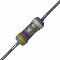
RES .47 OHM .50W 5% MF FUSIBLE
Manufacturer
Vishay
Series
NFR25Hr
Type
Metal Alloyr
Datasheet
1.NFR2500001008JR500.pdf
(10 pages)
Specifications of NFR25H0004707JR500
Resistance (ohms)
0.47
Power (watts)
0.5W, 1/2W
Composition
Metal Film
Features
Flame Proof, Fusible
Temperature Coefficient
±200ppm/°C
Tolerance
±5%
Size / Dimension
0.098" Dia x 0.295" L (2.50mm x 7.50mm)
Lead Style
Through Hole
Package / Case
Axial
Resistance In Ohms
0.47
Case
Axial
Power Rating(s)
1/2W
Resistance
470mOhm
Tolerance (+ Or -)
5%
Mounting Style
Through Hole
Construction
Axial
Case Style
Conformal
Military Standard
Not Required
Failure Rate
Not Required
Lead Spacing (nom)
Not Requiredmm
Product Length (mm)
7.5mm
Product Depth (mm)
Not Requiredmm
Product Height (mm)
Not Requiredmm
Resistance Tolerance
± 5%
Power Rating
500mW
Voltage Rating
350V
Resistor Element Material
Metal Film
Rohs Compliant
Yes
Lead Free Status / RoHS Status
Lead free / RoHS Compliant
Height
-
Lead Free Status / RoHS Status
Lead free / RoHS Compliant, Compliant
Other names
2322 207 23477
232220723477
5065FM0R470J12AFX
PPC.47BTR
232220723477
5065FM0R470J12AFX
PPC.47BTR


Document Number: 28737
Revision: 30-Mar-10
TEST PROCEDURES AND REQUIREMENTS
IEC
60115-1
CLAUSE
4.4.1
4.4.2
4.5
4.18
4.29
4.17
4.7
4.16
4.16.2
4.16.3
4.16.4
4.20
4.22
4.19
4.23
4.23.2
4.23.3
4.23.4
4.23.5
4.23.6
4.24
4.25.1
4.25.3
4.8
4.12
4.26
4.6.1.1
METHOD
60068-2
21 (Ua1)
78 (Cab)
21 (Ub)
21 (Uc)
29 (Eb)
14 (Na)
30 (Db)
30 (Db)
20 (Tb)
45 (Xa)
20 (Ta)
13 (M)
TEST
2 (Ba)
1 (Aa)
6 (Fc)
IEC
(refer note on first page for
Damp heat (accelerated)
Damp heat (accelerated)
Temperature coefficient
Resistance to soldering
category temperature
Bending half number
Endurance (at 70 °C)
Insulation resistance
Dimensions (outline)
measuring distance)
Component solvent
Endurance at upper
Accidental overload
Climatic sequence:
Visual examination
Tensile all samples
Torsion other half
Low air pressure
remaining cycles
Rapid change of
Robustness of
Voltage proof
(steady state)
terminations:
on insulation
Solderability
Solderability
temperature
(after aging)
Resistance
Damp heat
of samples
of samples
resistance
For technical questions, contact:
Vibration
Dry heat
1
Bump
st
Noise
TEST
Cold
heat
cycle
Fusible, Non-Flammable Metal Film
Leaded Resistors
for 2 s at 235 °C: Solder bath (SnPb40)
displacement 1.5 mm or acceleration
3 x 1500 bumps in 3 directions; 40 g
Maximum voltage
10 g; 3 directions; total 6 h (3 x 2 h)
56 days; 40 °C; 90 % to 95 % RH;
Solder bath method; SnAg3Cu0.5
5 days; 55 °C; 95 % to 100 % RH
1000 h; loaded with
after 1 min; metal block method
Applied voltage (+ 0 %/- 10 %):
24 h; 55 °C; 90 % to 100 % RH
3 x 360° in opposite directions
Between - 55 °C and + 155 °C
Solder bath method; SnPb40
for 3 s at 245 °C: Solder bath
Thermal shock: 10 s; 260 °C;
Frequency 10 Hz to 500 Hz;
2 h; 8.5 kPa; 15 °C to 35 °C
8 h steam or 16 h, 155 °C;
Isopropyl alcohol or H
10 kΩ ≤
RMS
(IEC steps: 0 V to 100 V)
10 Ω ≤
30 min at UCT; 5 cycles
1.5 h ON and 0.5 h OFF
leads immersed 6 mm;
(SnAg3Cu0.5) method
100 Ω ≤
1 kΩ ≤
followed by brushing
loaded with 0.01
metal block method
30 min at LCT and
0.22 Ω ≤ R ≤ 4.7 Ω
Load 5 N; 4 x 90°
15 Ω < R ≤ 15 kΩ
4.7 Ω < R ≤ 15 Ω
3 mm from body
Load 10 N; 10 s
= 500 V during 1 min;
1000 h; no load
PROCEDURE
Cheese-cloth
16 h; 155 °C
filmresistorsleaded@vishay.com
Gauge (mm)
2 s; 235 °C:
3 s; 245 °C:
2 h; - 55 °C
< 10 Ω: 0.1 V
IEC 60195
< 100 Ω: 0.3 V
< 10 kΩ: 3 V
≤ 15 kΩ: 10 V
< 1 kΩ: 1 V
max.
70
DC = 500 V
or
70
2
O
max.
;
Vishay BCcomponents
≤ ± 200 ppm/K
≤ ± 200 ppm/K
≤ ± 100 ppm/K
No holes; clean surface; no damage
Δ max.: ± (0.25 %
Good tinning (≥ 95 % covered);
Good tinning (≥ 95 % covered);
Δ max.: ± (0.25 %
Δ max.: ± (0.25 %
Δ max.: ± (0.25 %
Δ max.: ± (0.25 %
Number of failures < 10 x 10
Number of failures < 10 x 10
Δ max.: ± (1.5 %
NFR25
Δ max.: ± (1 %
Δ max.: ± (1 %
Δ max.: ± (1 %
No breakdown or flashover
NFR25, NFR25H
See Dimensions Table
REQUIREMENTS
No visual damage
No visual damage
-
Non flammable
ins
ins
ins
No damage
No damage
No damage
nom.
no damage
no damage
< 0.1 μV/V
min.: 10
min.: 10
min.: 10
: max. ± 5 %
≤ ± 200 ppm/K
≤ ± 100 ppm/K
≤ ± 100 ppm/K
3
3
4
www.vishay.com
+ 0.05 Ω)
+ 0.05 Ω)
+ 0.05 Ω)
MΩ
MΩ
MΩ
NFR25H
+ 0.05 Ω)
+ 0.05 Ω)
+ 0.05 Ω)
+ 0.05 Ω)
+ 0.05 Ω)
+ 0.1 Ω)
-6
-6
8
Related parts for NFR25H0004707JR500
Image
Part Number
Description
Manufacturer
Datasheet
Request
R

Part Number:
Description:
357-036-542-201 CARDEDGE 36POS DL .156 BLK LOPRO
Manufacturer:
Vishay
Datasheet:
Part Number:
Description:
357-036-542-201 CARDEDGE 36POS DL .156 BLK LOPRO
Manufacturer:
Vishay
Datasheet:
Part Number:
Description:
357-036-542-201 CARDEDGE 36POS DL .156 BLK LOPRO
Manufacturer:
Vishay
Datasheet:
Part Number:
Description:
357-036-542-201 CARDEDGE 36POS DL .156 BLK LOPRO
Manufacturer:
Vishay
Datasheet:
Part Number:
Description:
357-036-542-201 CARDEDGE 36POS DL .156 BLK LOPRO
Manufacturer:
Vishay
Datasheet:
Part Number:
Description:
357-036-542-201 CARDEDGE 36POS DL .156 BLK LOPRO
Manufacturer:
Vishay
Datasheet:
Part Number:
Description:
357-036-542-201 CARDEDGE 36POS DL .156 BLK LOPRO
Manufacturer:
Vishay
Datasheet:
Part Number:
Description:
357-036-542-201 CARDEDGE 36POS DL .156 BLK LOPRO
Manufacturer:
Vishay
Datasheet:
Part Number:
Description:
357-036-542-201 CARDEDGE 36POS DL .156 BLK LOPRO
Manufacturer:
Vishay
Datasheet:
Part Number:
Description:
357-036-542-201 CARDEDGE 36POS DL .156 BLK LOPRO
Manufacturer:
Vishay
Datasheet:
Part Number:
Description:
357-036-542-201 CARDEDGE 36POS DL .156 BLK LOPRO
Manufacturer:
Vishay
Datasheet:
Part Number:
Description:
357-036-542-201 CARDEDGE 36POS DL .156 BLK LOPRO
Manufacturer:
Vishay
Datasheet:
Part Number:
Description:
357-036-542-201 CARDEDGE 36POS DL .156 BLK LOPRO
Manufacturer:
Vishay
Datasheet:
Part Number:
Description:
357-036-542-201 CARDEDGE 36POS DL .156 BLK LOPRO
Manufacturer:
Vishay
Datasheet:
Part Number:
Description:
357-036-542-201 CARDEDGE 36POS DL .156 BLK LOPRO
Manufacturer:
Vishay
Datasheet: