FX12B-24S-0.4SV Hirose Electric Co Ltd, FX12B-24S-0.4SV Datasheet - Page 8
FX12B-24S-0.4SV
Manufacturer Part Number
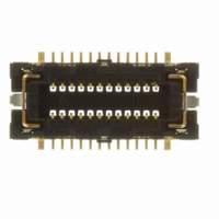
FX12B-24S-0.4SV
Description
CONN RCPT 24POS 0.4MM SMD SHIELD
Manufacturer
Hirose Electric Co Ltd
Series
FX12r
Datasheet
1.FX12B-24S-0.4SV.pdf
(10 pages)
Specifications of FX12B-24S-0.4SV
Pitch
0.016" (0.40mm)
Connector Type
Receptacle, Outer Shroud Contacts
Number Of Positions
24
Number Of Rows
2
Mounting Type
Surface Mount
Features
Solder Retention
Contact Finish
Gold
Mated Stacking Heights
1.5mm
Height Above Board
0.047" (1.20mm)
Product Type
Receptacles
Mounting Style
SMD/SMT
Mounting Angle
Vertical
Number Of Positions / Contacts
24
Contact Material
Phosphor Bronze
Contact Plating
Gold
Voltage Rating
30 V
Current Rating
0.3 A
Lead Free Status / RoHS Status
Lead free / RoHS Compliant
Contact Finish Thickness
-
Lead Free Status / Rohs Status
Lead free / RoHS Compliant
Other names
H11406TR
Available stocks
Company
Part Number
Manufacturer
Quantity
Price
Company:

Part Number:
FX12B-24S-0.4SV
Manufacturer:
CK
Quantity:
450
Company:
Part Number:
FX12B-24S-0.4SV
Manufacturer:
Hirose Electric Co Ltd
Quantity:
3 000
Company:
Part Number:
FX12B-24S-0.4SV(30)
Manufacturer:
Hirose Electric Co Ltd
Quantity:
12 000


A270
The product information in this catalog is for reference only. Please request the Engineering Drawing for the most current and accurate design information.
All non-RoHS products have been discontinued, or will be discontinued soon. Please check the products status on the Hirose website RoHS search at www.hirose-connectors.com, or contact your Hirose sales representative.
FX12 Series●0.4 mm Pitch, 1.5 mm Board-to-Board Connectors with Dual Shields
BHandling Precautions when mating mounted connectors.
Caution
When the connectors are mounted on the FPC, special care should be excercised NOT to have the forces of the FPC’s bend
or twist affecting the fully mated connectors.
Device case or cushioning material should be used to keep connectors fully mated.
MAX 0.3
FX12*-**S-0.4SV
FX12*-**P-0.4SV
Fig.1
MAX 0.3
Start the engagement of the connectors within the specified
self-alignment range of 0.3 mm, while keeping the boards
parallel to each other.
Do NOT start mating of the mounted connectors under an
angle.
Correctly position the connectors over each other and assure
that both boards are parallel to each other.
When the connectors are correctly aligned (and both boards are
parallel to each other) apply even force until full mating is
confirmed by the “click” sensation.
Related parts for FX12B-24S-0.4SV
Image
Part Number
Description
Manufacturer
Datasheet
Request
R

Part Number:
Description:
Board to Board / Mezzanine Connectors 24P SMT RECEP 1.5MM .4MM PITCH
Manufacturer:
Hirose Electric Co Ltd

Part Number:
Description:
CONN PLUG 24POS 0.4MM SMD SHIELD
Manufacturer:
Hirose Electric Co Ltd
Datasheet:

Part Number:
Description:
CONN PLUG 40POS 0.4MM SMD SHIELD
Manufacturer:
Hirose Electric Co Ltd
Datasheet:

Part Number:
Description:
CONN RCPT 40POS 0.4MM SMD SHIELD
Manufacturer:
Hirose Electric Co Ltd
Datasheet:

Part Number:
Description:
CONN RCPT 60POS 0.4MM SMD SHIELD
Manufacturer:
Hirose Electric Co Ltd
Datasheet:
Part Number:
Description:
Conn Rectangular PL 14 POS 2.54mm Crimp RA Cable Mount
Manufacturer:
Hirose Electric Co Ltd
Part Number:
Description:
Conn Shrouded Header HDR 10 POS 2mm Solder ST SMD Embossed T/R
Manufacturer:
Hirose Electric Co Ltd
Datasheet:
Part Number:
Description:
DF11-20DP-2DSA(24)
Manufacturer:
Hirose Electric Co Ltd
Datasheet:
Part Number:
Description:
Conn Shrouded Header HDR 6 POS 2mm Solder ST Thru-Hole Bag
Manufacturer:
Hirose Electric Co Ltd
Datasheet:
Part Number:
Description:
Conn Shrouded Header HDR 8 POS 2mm Solder ST Thru-Hole Tube
Manufacturer:
Hirose Electric Co Ltd
Datasheet:
Part Number:
Description:
Conn Shrouded Header HDR 26 POS 2mm Solder ST SMD
Manufacturer:
Hirose Electric Co Ltd
Datasheet:
Part Number:
Description:
Conn Shrouded Header HDR 22 POS 2mm Solder ST SMD
Manufacturer:
Hirose Electric Co Ltd
Part Number:
Description:
Conn Shrouded Header HDR 22 POS 2mm Solder ST SMD
Manufacturer:
Hirose Electric Co Ltd
Part Number:
Description:
2mm 22w Wire to Board IDC Crimp Connector
Manufacturer:
Hirose Electric Co Ltd