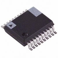
ADE7761AARS-RL Analog Devices Inc, ADE7761AARS-RL Datasheet - Page 20

ADE7761AARS-RL
Manufacturer Part Number
ADE7761AARS-RL
Description
IC DETECTOR ENERGY METER 20-SSOP
Manufacturer
Analog Devices Inc
Datasheet
1.ADE7761AARSZ-RL.pdf
(24 pages)
Specifications of ADE7761AARS-RL
Input Impedance
400 KOhm
Measurement Error
0.1%
Voltage - I/o High
2.4V
Voltage - I/o Low
0.8V
Current - Supply
3mA
Voltage - Supply
4.75 V ~ 5.25 V
Operating Temperature
-40°C ~ 85°C
Mounting Type
Surface Mount
Package / Case
20-SSOP (0.200", 5.30mm Width)
Meter Type
Single Phase
Lead Free Status / RoHS Status
Contains lead / RoHS non-compliant
ADE7761A
Missing Neutral Gain Calibration
When the ADE7761A is in missing neutral mode, the energy is
bill based on the active current input signal level. The frequency
outputs in this mode can be calibrated with the MISCAL analog
input pin. In this mode, applying a dc voltage of 330 mV on
MISCAL is equivalent to applying, in normal mode, a pure sine
wave on the voltage input with a peak value of 330 mV. The
MISCAL input can vary from 0 V to 660 mV (see the Analog
Inputs section). When set to 0 V, the frequency outputs are
close to zero. When set to 660 mV dc, the frequency outputs are
twice that when MISCAL is at 330 mV dc. In other words,
Equation 7 can be used in missing neutral mode by replacing
V2
where:
F
V1
MISCAL
pin (V).
Gain is 1 or 16, depending on the PGA gain selection made
using logic input PGA.
V
F
logic inputs S0 and S1 (see Table 6).
1
1-4
REF
, F
rms
rms
is one of four possible frequencies selected by using the
2
is the reference voltage (2.5 V ± 8%) (V).
F
. 5
is the differential rms voltage signal on Channel 1 (V).
by MISCAL
Frequency is the output frequency on F
1
,
70
F
rms
2
×
Frequency
Gain
is the differential rms voltage signal on the MISCAL
×
rms
V
1
/√2.
rms
=
V
×
REF
MISCAL
2
rms
/
2
×
F
1
1
−
and F
4
2
(Hz).
Rev. 0 | Page 20 of 24
(8)
Example
In normal mode, ac voltages of ±330 mV peak are applied to V1
and V2, and then the expected output frequency on F
calculated as:
In missing neutral mode, the ac voltage of ±330 mV peak is
applied to V1, no signal is connected on V2, and a 330 mV dc
input is applied to MISCAL. With the ADE7761A in the same
configuration as the previous example, the expected output
frequencies on CF, F
CF Frequency = F
CF Frequency = F
Gain =1 ; PGA =0
F
V1 = rms of 330 mV peak ac = 0.33/√2 V
V2 = rms of 330 mV peak ac = 0.33/√2 V
V
F
F
1
1–4
1
REF
,
,
F
F
= 1.7 Hz, SCF = S1 = S0 = 0
2
2
= 2.5 V (nominal reference value)
Frequency
Frequency
1
, and F
=
=
1
1
, F
− F
. 5
. 5
70
2
70
Frequency × 64 = 5.4 Hz
2
2
×
Frequency × 64 = 5.4 Hz
×
are
. 0
. 0
2
33
33
×
×
×
2
. 0
2
. 0
×
33
×
33
2
2
5 .
/
5 .
×
2
1
2
2
7 .
×
Hz
1
7 .
Hz
=
. 0
084
=
1
and F
. 0
084
Hz
2
Hz
is


