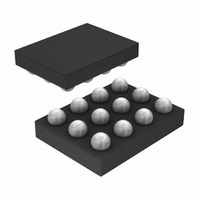
LM3530UME-25A/NOPB National Semiconductor, LM3530UME-25A/NOPB Datasheet - Page 30

LM3530UME-25A/NOPB
Manufacturer Part Number
LM3530UME-25A/NOPB
Description
IC LED DRVR PRGRAM I2C 10LED SMD
Manufacturer
National Semiconductor
Series
PowerWise®r
Datasheet
1.LM3530UME-40NOPB.pdf
(44 pages)
Specifications of LM3530UME-25A/NOPB
Topology
PWM, Step-Up (Boost)
Number Of Outputs
1
Internal Driver
Yes
Type - Primary
Backlight
Type - Secondary
White LED
Frequency
500kHz
Voltage - Supply
2.7 V ~ 5.5 V
Mounting Type
Surface Mount
Package / Case
12-XFBGA
Operating Temperature
-40°C ~ 85°C
Current - Output / Channel
Adjustable
Lead Free Status / RoHS Status
Lead free / RoHS Compliant
Voltage - Output
-
Other names
LM3530UME-25A/NOPBTR
www.national.com
ALS RESISTOR SELECT REGISTER
The ALS Resistor Select Register configures the internal re-
sistance from either the ALS1 or ALS2 input to GND. Bits [3:0]
program the input resistance at the ALS1 input and bits [7:4]
BRIGHTNESS CONTROL REGISTER
The Brightness Register (BRT) is an 8-bit register that pro-
grams the 127 different LED current levels (Bits [6:0]). The
code written to BRT is translated into an LED current as a
percentage of I
Select bits (General Configuration Register bits [4:2]). The
LED current response has a typical 1000:1 dimming ratio at
the maximum full-scale current (General Configuration Reg-
ister bits [4:2] = (111) and using the exponential weighted
dimming curve.
Bit 7
Bit 7
(ALSR2A)
0000 = ALS2 is high impedance
0001 = 13.531kΩ (73.9µA at 1V)
0010 =9.011kΩ (111µA at 1V)
0011 = 5.4116kΩ (185µA at 1V)
0100 = 2.271kΩ (440µA at 1V)
0101 = 1.946kΩ (514µA at 1V)
0110 = 1.815kΩ (551µA at 1V)
0111 = 1.6kΩ (625µA at 1V)
1000 = 1.138kΩ (879µA at 1V)
1001 = 1.05kΩ (952µA at 1V)
1010 = 1.011kΩ (989µA at 1V)
1011 = 941Ω (1.063mA at 1V)
1100 = 759Ω (1.318mA at 1V)
1101 = 719Ω (1.391mA at 1V)
1110 =700Ω (1.429mA at 1V)
1111 = 667Ω (1.499mA at 1V)
N/A
Bit 6
N/A
LED_FULLSCALE
Bit 5
N/A
Bit 6
(ALSR2B
)
as set via the Full-Scale Current
Bit 4
TABLE 8. ALS Zone Information Register Description (0x40)
N/A
TABLE 9. ALS Resistor Select Register Description (0x41)
Bit 5
(ALSR2C)
Bit 3
(Zone Boundary Change
Flag)
1 = the active ALS input has
changed to a new ambient
light zone as a programmed in
the Zone Boundary Registers
(ZB0 -ZB3)
0 = no zone change
FIGURE 22. ALS Resistor Select Register
Bit 4
(ALSR2D)
30
program the input resistance at the ALS2 input. With bits [3:0]
set to all zeroes the ALS1 input is high impedance. With bits
[7:4] set to all zeroes the ALS2 input is high impedance.
There are two selectable LED current profiles. Setting the
General Configuration Register bit 1 to 0 selects the expo-
nentially weighted LED current response (see
Setting this bit to '1' selects the linear weighted curve (see
Figure
Scale LED Current at a given Brightness Register Code for
both the Exponential and Linear current response.
Bit 3
(ALSR1A)
0000 = ALS2 is high impedance
0001 = 13.531kΩ (73.9µA at 1V)
0010 =9.011kΩ (111µA at 1V)
0011 = 5.4116kΩ (185µA at 1V)
0100 = 2.271kΩ (440µA at 1V)
0101 = 1.946kΩ (514µA at 1V)
0110 = 1.815kΩ (551µA at 1V)
0111 = 1.6kΩ (625µA at 1V)
1000 = 1.138kΩ (879µA at 1V)
1001 = 1.05kΩ (952µA at 1V)
1010 = 1.011kΩ (989µA at 1V)
1011 = 941Ω (1.063mA at 1V)
1100 = 759Ω (1.318mA at 1V)
1101 = 719Ω (1.391mA at 1V)
1110 =700Ω (1.429mA at 1V)
1111 = 667Ω (1.499mA at 1V)
Bit 2
(Z2)
000 = Zone 0
001 = Zone 1
010 = Zone 2
011 = Zone 3
100 = Zone 4
12).
Table 2
and
Bit 2
(ALSR1B)
Bit 1
(Z1)
Table 3
30086634
show the percentage Full-
Bit 1
(ALSR1C)
Bit 0
(Z0)
Bit 0
(ALSR1D)
Figure
11).


