STEVAL-PCC012V1 STMicroelectronics, STEVAL-PCC012V1 Datasheet - Page 10
STEVAL-PCC012V1
Manufacturer Part Number
STEVAL-PCC012V1
Description
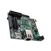
BOARD DEM CONN GATEWAY STM32F107
Manufacturer
STMicroelectronics
Series
STM32r
Type
Other Power Managementr
Datasheets
1.STM32F105V8T6.pdf
(101 pages)
2.STEVAL-PCC012V1.pdf
(10 pages)
3.EVALST7590-1.pdf
(43 pages)
Specifications of STEVAL-PCC012V1
Main Purpose
Interface, Connectivity
Embedded
Yes, MCU, 32-Bit
Utilized Ic / Part
STM32F107
Primary Attributes
Ethernet and 4 Digital/Analog Connectors
Secondary Attributes
On-Board LEDs and Joystick
Interface Type
Ethernet, USB, I2C, SPI, UART
Operating Supply Voltage
3.3 V
Product
Power Management Development Tools
Lead Free Status / RoHS Status
Lead free / RoHS Compliant
For Use With/related Products
STM32F107xx
Other names
497-10757
Available stocks
Company
Part Number
Manufacturer
Quantity
Price
Company:

Part Number:
STEVAL-PCC012V1
Manufacturer:
STMicroelectronics
Quantity:
1


Configuration
5
5.1
10/43
Configuration
Ethernet
An Ethernet PHY U5 is available on the board. It is connected through the media
independent interfaces (MII, and reduced MII, RMII) to the Ethernet MACs of the STM32™
microcontroller.
If the Ethernet PHY is used, the crystal resonator X2 must be chosen as STM32 clock
source.
The clock source for the PHY is the clock output MCO signal of the STM32 microcontroller.
To operate in MII mode, the MCO signal must be configured to output 25 MHz, for RMII,
50 MHz.
By default the MII address of the Ethernet PHY is 0x01 and the initial configuration of the
Ethernet PHY is selected as shown in
Table 2.
There are two LEDs embedded in RJ45 connector (CN5) which are used to indicate the
status of the line:
●
●
The “Serial Management Interface” (SMI) is part of the MII interface and is used to transfer
management information between MAC and PHY (access of the PHY registers).
The PHY can communicate with the STM32 microcontroller over MII or RMII. SB1, SB2 and
SB3 must be configured according to the mode chosen. MII is chosen as a default option.
Table 3.
Auto negotiation
10/100 Mb
Half/full duplex
Internal loopback
Power-down
MII/RMII mode
The green LED in the connector is switched on continuously when the Ethernet link is
established with the counterpart.
The yellow LED in the connector blinks when a transmission or a reception is ongoing.
Function
Function
Default configuration of the Ethernet PHY
Ethernet PHY configuration defined by SB1, SB2 and SB3
SB1
SB2
SB3
Doc ID 17009 Rev 1
Enabled
100 Mb selected for auto negotiation advertisement
Full duplex selected for auto negotiation advertisement
Disabled
Disabled (PHY is not in power-down)
MII selected
Table
Fit 0 Ω resistor
Removed
Removed
MII
2.
Default configuration
Fit 0 Ω resistor
Fit 0 Ω resistor
Removed
RMII
UM0896
Related parts for STEVAL-PCC012V1
Image
Part Number
Description
Manufacturer
Datasheet
Request
R

Part Number:
Description:
Interface Development Tools Opto ISO USB Bridge 8-Pin Motor CTRL BRD
Manufacturer:
STMicroelectronics
Datasheet:

Part Number:
Description:
BOARD EVAL FOR MEMS SENSORS
Manufacturer:
STMicroelectronics
Datasheet:
Part Number:
Description:
EVALBOARD/STEVAL-ISV014V1
Manufacturer:
STMicroelectronics
Part Number:
Description:
BOARD EVAL FOR ST802RT1
Manufacturer:
STMicroelectronics
Datasheet:

Part Number:
Description:
BOARD EVAL FOR VACUUM CLEANER
Manufacturer:
STMicroelectronics
Datasheet:

Part Number:
Description:
KIT DEV STARTER ST10F276Z5
Manufacturer:
STMicroelectronics
Datasheet:

Part Number:
Description:
BOARD LED CTLR/DVR STLED316S
Manufacturer:
STMicroelectronics
Datasheet:

Part Number:
Description:
BOARD EVAL BLDC SENSORLESS MOTOR
Manufacturer:
STMicroelectronics
Datasheet:

Part Number:
Description:
BOARD ELECT FISCAL CASH REGISTER
Manufacturer:
STMicroelectronics
Datasheet:

Part Number:
Description:
BOARD EVAL BIPO SOLUTION FOR PFC
Manufacturer:
STMicroelectronics
Datasheet:
Part Number:
Description:
STMicroelectronics [RIPPLE-CARRY BINARY COUNTER/DIVIDERS]
Manufacturer:
STMicroelectronics
Datasheet:
Part Number:
Description:
STMicroelectronics [LIQUID-CRYSTAL DISPLAY DRIVERS]
Manufacturer:
STMicroelectronics
Datasheet:
Part Number:
Description:
BOARD EVAL FOR MEMS SENSORS
Manufacturer:
STMicroelectronics
Datasheet: