TWR-S08MM128 Freescale Semiconductor, TWR-S08MM128 Datasheet - Page 9
TWR-S08MM128
Manufacturer Part Number
TWR-S08MM128
Description
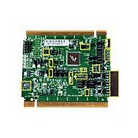
TOWER SYSTEM BOARD MC9S08MM128
Manufacturer
Freescale Semiconductor
Series
ColdFire®, Flexis™r
Type
MCUr
Datasheets
1.TWR-S08MM128.pdf
(12 pages)
2.TWR-S08MM128.pdf
(13 pages)
3.MC9S08MM128CMB.pdf
(52 pages)
Specifications of TWR-S08MM128
Contents
Board
Processor To Be Evaluated
9S08MM128
Data Bus Width
8 bit
Interface Type
USB, CAN
Silicon Manufacturer
Freescale
Core Architecture
Coldfire, HCS08
Core Sub-architecture
Coldfire V1, HCS08
Silicon Core Number
MCF51, MC9S08
Silicon Family Name
Flexis - MCF51MM, Flexis - S08MM
Rohs Compliant
Yes
For Use With/related Products
Freescale Tower System, MC9S08MM128
Lead Free Status / RoHS Status
Lead free / RoHS Compliant


Jumper
J10
J11
J12
J13
J14
J15
J16
J18
J19
J1
J2
J3
J4
J5
J6
J7
J8
J9
DADP0 routing selection
DADM0 routing selection
VINP1 routing selection
Potentiometer connection
DACO routing selection
DACO routing selection
TRIAMP routing selection
TRIAMP routing selection
Infrared receive routing
USB3.3V connection
MCU IDD measure
OSBDM Bootloader mode or
debugger mode selection
BDM connector for
MC9S08MM128
BDM connector for JM60
SCI2 TXD Routing Selection
SCI2 RXD Routing Selection
LED & Accelerometer
connections
Accelerometer mode control
Option
Figure 5. TWR‐S08MM128 Jumper Table
TWR‐MC9S08MM128 User Manual
Setting
11‐12 Connects ADP7 to ACCY
13‐14 Connects ADP6 to ACCX
Open OSBDM IC in debugger mode .
Open BDM connector for MC9S08MM128
Open BDM connector for MC9S08JM60
9‐10 Connects ADP8 to ACCZ
1‐2
1‐2
1‐2
2‐3
1‐2
1‐2
2‐3
1‐2
1‐2
2‐3
1‐2
2‐3
1‐2
1‐2
2‐3
1‐2
1‐2
1‐2
2‐3
1‐2
2‐3
1‐2
3‐4
5‐6
7‐8
1‐2
3‐4
5‐6
Connect DADP0 to medical connector J27 pin 5
Connect DADM0 to medical connector J27 pin 6
VINP1 connect to GND
VINP1 optionally connected to DACO
Connection of ADP4 to potentiometer
Connect DACO to VINP1 if pin 2‐3 of J3 is connected
Connect DACO to a RC low pass filter
Connect DACO to medical connector J27 pin 8
Connect TRIOUT1 to TRIOUT_SEL2
Connect TRIOUT2 to TRIOUT_SEL2
Connect TRIOUT1 to TRIOUT_SEL1
Connect TRIOUT2 to TRIOUT_SEL1
Connect Infrared transistor output to CMPP1
USB3.3V connects to external 3.3V power supply
USB3.3V connects to on‐chip USB 3.3V regulator output
For measuring MC9S08MM128 current
OSBDM IC in bootloader mode(For OSBDM firmware
reprogramming)
Connect TX2 to the RS232 transceiver
Connect TX2 to the OSBDM debugger interface circuit
Connect RX2 to the RS232 transceiver
Connect RX2 to the OSBDM debugger interface circuit
Connects LED4 to pin PTE7/TPM2CH3
Connects LED3 to pin PTF0/TPM2CH2
Connects LED2 to pin PTF1/RX2/TPM2CH1
Connects LED1 to pin PTF2/TX2/TPM2CH0
Connects PTA3 to SELF TEST pin of accelerometer
Connects PTA6 to
Connects PTA5 to G‐SELECT pin of accelerometer
Description of MC9S08MM128 signal routing
SLEEP
pin of accelerometer
Page 9 of 13
Related parts for TWR-S08MM128
Image
Part Number
Description
Manufacturer
Datasheet
Request
R

Part Number:
Description:
Development Boards & Kits - S08 / S12 S08PT60 Tower Kit
Manufacturer:
Freescale Semiconductor
Datasheet:
Part Number:
Description:
Development Boards & Kits - S08 / S12 S08PT60Tower MCU mod
Manufacturer:
Freescale Semiconductor
Datasheet:
Part Number:
Description:
TOWER UNIVERSAL RS08/S08
Manufacturer:
Freescale Semiconductor
Datasheet:

Part Number:
Description:
Manufacturer:
Freescale Semiconductor, Inc
Datasheet:
Part Number:
Description:
Manufacturer:
Freescale Semiconductor, Inc
Datasheet:
Part Number:
Description:
Manufacturer:
Freescale Semiconductor, Inc
Datasheet:
Part Number:
Description:
Manufacturer:
Freescale Semiconductor, Inc
Datasheet:
Part Number:
Description:
Manufacturer:
Freescale Semiconductor, Inc
Datasheet:
Part Number:
Description:
Manufacturer:
Freescale Semiconductor, Inc
Datasheet:
Part Number:
Description:
Manufacturer:
Freescale Semiconductor, Inc
Datasheet:
Part Number:
Description:
Manufacturer:
Freescale Semiconductor, Inc
Datasheet:
Part Number:
Description:
Manufacturer:
Freescale Semiconductor, Inc
Datasheet:
Part Number:
Description:
Manufacturer:
Freescale Semiconductor, Inc
Datasheet:
Part Number:
Description:
Manufacturer:
Freescale Semiconductor, Inc
Datasheet:
Part Number:
Description:
Manufacturer:
Freescale Semiconductor, Inc
Datasheet: