TWR-K40X256-KIT Freescale Semiconductor, TWR-K40X256-KIT Datasheet - Page 4
TWR-K40X256-KIT
Manufacturer Part Number
TWR-K40X256-KIT
Description
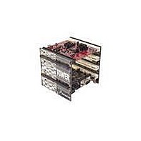
TOWER SYSTEM KIT K40X256
Manufacturer
Freescale Semiconductor
Series
Kinetisr
Type
MCUr
Specifications of TWR-K40X256-KIT
Contents
4 Boards, Documentation, DVD
Processor To Be Evaluated
K40
Data Bus Width
32 bit
Interface Type
RS-232, USB, CAN, I2C, SPI, UART
Dimensions
3.5 in x 3.5 in x 3.5 in
Operating Supply Voltage
1.71 V to 3.6 V
Silicon Manufacturer
Freescale
Core Architecture
ARM
Core Sub-architecture
Cortex - M4
Silicon Core Number
MK
Silicon Family Name
Kinetis - K40
Kit Contents
4x Brds, Cable, Docs
Rohs Compliant
Yes
For Use With/related Products
Freescale Tower System, K40X256
Lead Free Status / RoHS Status
Lead free / RoHS Compliant


Step-by-Step Installation Instructions
In this Quick Start Guide, you will learn how to set up the TWR-K40X256
module and run the default demonstration.
Install the P&E Micro Kinetis Tower Toolkit
to install the OSJTAG and USB-to-Serial
drivers. These can be found on the DVD
under Software.
the VBAT (RTC) battery holder. Then plug
in the included Segment LCD Tower
Plug-In (TWRPI-SLCD) into the Touch/
SLCD TWRPI socket. Finally, connect one
end of the USB cable to the PC and the
other end to the Power/OSJTAG mini-B
connector on the TWR-K40X256 module.
Allow the PC to automatically configure
the USB drivers if needed.
TOWER SYSTEM
STEP
STEP
1
2
Install the Software
and Tools
Configure the Hardware
Install the included battery into
The Segment LCD will come up
displaying the seconds elapsed since
boot-up. Press SW4 to toggle between
viewing the seconds, hours and minutes,
potentiometer percent, and temperature.
see the LEDs on E1–E4 light up as
it is tilted.
STEP
STEP
3
4
Tilt the Board
Tilt the board side to side to
Navigate the
Segment LCD
Related parts for TWR-K40X256-KIT
Image
Part Number
Description
Manufacturer
Datasheet
Request
R

Part Number:
Description:
Manufacturer:
Freescale Semiconductor, Inc
Datasheet:
Part Number:
Description:
Manufacturer:
Freescale Semiconductor, Inc
Datasheet:
Part Number:
Description:
Manufacturer:
Freescale Semiconductor, Inc
Datasheet:
Part Number:
Description:
Manufacturer:
Freescale Semiconductor, Inc
Datasheet:
Part Number:
Description:
Manufacturer:
Freescale Semiconductor, Inc
Datasheet:
Part Number:
Description:
Manufacturer:
Freescale Semiconductor, Inc
Datasheet:
Part Number:
Description:
Manufacturer:
Freescale Semiconductor, Inc
Datasheet:
Part Number:
Description:
Manufacturer:
Freescale Semiconductor, Inc
Datasheet:
Part Number:
Description:
Manufacturer:
Freescale Semiconductor, Inc
Datasheet:
Part Number:
Description:
Manufacturer:
Freescale Semiconductor, Inc
Datasheet:
Part Number:
Description:
Manufacturer:
Freescale Semiconductor, Inc
Datasheet:
Part Number:
Description:
Manufacturer:
Freescale Semiconductor, Inc
Datasheet:
Part Number:
Description:
Manufacturer:
Freescale Semiconductor, Inc
Datasheet:
Part Number:
Description:
Manufacturer:
Freescale Semiconductor, Inc
Datasheet:
Part Number:
Description:
Manufacturer:
Freescale Semiconductor, Inc
Datasheet: