101-0722 Rabbit Semiconductor, 101-0722 Datasheet - Page 3

101-0722
Manufacturer Part Number
101-0722
Description
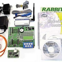
KIT APPLICATION M2M INT'L
Manufacturer
Rabbit Semiconductor
Series
RabbitCore 3000r
Type
M2M (Machine to Machine)r
Datasheet
1.101-0722.pdf
(4 pages)
Specifications of 101-0722
Contents
Programmer/Debugger
Wireless Frequency
900 MHz to 1.8 GHz
Interface Type
RS-232, Ethernet
For Use With/related Products
RCM3200
Lead Free Status / RoHS Status
Contains lead / RoHS non-compliant
Other names
101-722
101-722
101-722
Application Kits Outside North America
Application kits sold outside North America include a header connector that may be connected to 3-pin
header J9 on the Prototyping Board. The connector may be attached either way as long as it is not offset
to one side.The red and black wires from the connector can then be connected to the positive and nega-
tive connections on your power supply. The power supply should deliver 8 V–24 V DC at 1 A.
3. Attach Cables
Connect the 10-pin connector of
the programming cable labeled
PROG to header J3 on the
RCM3200 as shown in Figure 3.
Be sure to orient the marked
(usually red) edge of the cable
towards pin 1 of the connector.
(Do not use the DIAG connector,
which is used for a normal serial
connection.)
4. Set Up GSM/GPRS Modem
The modem requires a SIM card, and sup-
ports both 3 V and 5 V SIM cards. Before
using your SIM card, contact your service
provider to activate your card as detailed in
the instructions included with your card.
North American customers may call
AIRDESK at 1-800-AIR-DESK to get a
SIM card, and make arrangements for
wireless service and activation. You may
have to wait 8–24 hours for the activation
to come into effect. You may also be asked
for the 15-digit IMEI number of the
modem, which appears with the bar code
label on the modem.
Use a small screwdriver to pry off the SIM
cover on Multi-Tech modems; for Wave-
com modems, use a pointed object to press
the yellow button near the antenna con-
nector to eject the SIM card holder. Place the SIM card, and return the card holder into the modem.
Use the DB15 to 10-pin adapter cable to connect the modem to the RS-232 header on the Prototyping
Board. Be sure to orient the marked (usually red) edge of the adapter cable towards pin 1 of the con-
nector. Install the antenna and connect the 12 V, 1 A power adapter as shown in Figure 4.
NOTE: Be sure to use the pro-
gramming cable supplied
with this Application Kit—
the programming cable has
blue shrink wrap around the
RS-232 converter section located in the middle of the cable. Programming cables from other
Z-World or Rabbit Semiconductor kits were not designed to work with RCM3200 modules.
Figure 3. Connect Programming and Ethernet Cables to PC
Figure 4. Hook Up GSM/GPRS Modem


