RF3806TR7 RFMD, RF3806TR7 Datasheet - Page 8
RF3806TR7
Manufacturer Part Number
RF3806TR7
Description
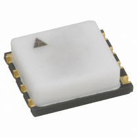
IC AMP HBT GAAS PRE-DVR 4W AIN
Manufacturer
RFMD
Datasheet
1.RF3806TR7.pdf
(20 pages)
Specifications of RF3806TR7
Current - Supply
660mA ~ 800mA
Frequency
1.5GHz ~ 2.2GHz
Gain
17dB ~ 19dB
P1db
35dBm ~ 37dBm
Package / Case
8-LCC
Rf Type
W-CDMA, SATCOM, DCS, PCS, UMTS
Test Frequency
2.11GHz ~ 2.17GHz
Voltage - Supply
5V ~ 8V
Lead Free Status / RoHS Status
Lead free / RoHS Compliant
Noise Figure
-
Other names
689-1026-2
Available stocks
Company
Part Number
Manufacturer
Quantity
Price

Part Number:
RF3806TR7
Manufacturer:
RFMD
Quantity:
20 000


RF3806
General biasing considerations can be described using RF3806 UMTS evaluation board as a reference. In actual system,
V
V
various supply voltage levels (more detailed discussion below).
RF3806 can be used in frequency bands ranging from 1500MHz to 2200MHz. Depending on specific application, the follow-
ing parameters and their trade-offs can be considered: linearity, average output power, signal modulation/peak to average
ratio (PAR), efficiency, dissipated power, junction temperature (Tj), and wear out MTTF. Looking at two distinct examples will
demonstrate how the above mentioned parameters are taken into account. Note that much of the discussed performance can
be found in the data sheet area showing graphs.
First, consider a UMTS pico cell base station transmitter (case 1). Here RF3806 fills the role of final PA, operating from
21dBm-26dBm P
from 41mA -60mA. The choice of voltage supply and bias is determined by required W-CDMA ACPR spec, desired P
nal PAR. For instance, consider the following: P
64 DPCH, ACPR requirement over temperature=-45dBc at 5MHz offset. The operating condition here (see data sheet graph
section) would be V
power requirement, I
P
ations, refer to graphs provided for thermal resistance, junction temperature, and MTTF (these three graphs based on RF3806
thermal scan and process reliability data).
For the second example (case 2), consider a higher power application, where P
stantially reduced from that seen in above example. For this application, we might run I
put load line would be set for maximum efficiency and compression point. The result is a transmit PA which obtains output
power spec, while providing high enough efficiency to keep Tj within desired range. Running I
power dissipation, as higher I
is provided in data sheet for higher power applications, along with corresponding information in section containing graphs.
UMTS evaluation board can be converted to the application schematic, with minor changes to input, output, and interstage
matches (interstage @V
the graph section. Note that the matching also covers transmit bands for 1850-1910 CDMA. As a result, this converted appli-
cation board could also be considered for CDMA booster/repeater.
As mentioned above, junction temperature is an important consideration when operating at maximum V
demanding scenario, case 1 above, will be considered here as an illustration. In the data sheet graph section, refer to graphs
of Tj vs P
perature controlled stage, held at ambient. The device is etched open, such that thermal image of die can be taken. Reference
temperature is measured at evaluation board to stage interface by thermocouple, placed through a thin groove such that it
makes contact with underside eval board GND plane (directly beneath RF3806). Thermocouple measures "reference tempera-
ture", from which R
modeled at 1°C/W. Knowing these two values allows us to calculate junction to case thermal resistance of
RF3806=R
GND slug of device.
8 of 20
CC
BIAS
OUT
=V
, while the decrease in dissipated power yields a lower junction temperature and enhanced MTTF. For thermal consider-
, and V
BIAS
OUT
=V
TH_JC
REF
, R
REF
TH
used for turn-on preceding transmit. Table is provided in data sheet for adjusting I
=R
can be tied together when PA is to remain biased on at all times. For non-constant operation, V
vs P
OUT
TH_JREF
TH_JREF
CC
REF
. V
OUT
=8V and I
CC1
CC
, and RF3806 wear out MTTF vs Tj. During thermal scan, RF3806 eval board is affixed to a large, tem-
is kept at 60mA, and V
-R
can be run from 5V to 8V. Likewise, bias resistance on V
(junction to reference) is determined. Evaluation board thermal resistance, R
pin). Also, bias resistors at V
REF
TH_BOARD
7628 Thorndike Road, Greensboro, NC 27409-9421 · For sales or technical
support, contact RFMD at (+1) 336-678-5570 or sales-support@rfmd.com.
is used only in lower power case for linearity enhancement. A DCS/PCS application schematic
REF
=60mA, using impedance match found on UMTS Evaluation Board. For a lower output
=R
TH_JREF
Theory of Operation
OUT
-1 (see graph). Thus, R
CC
=26dBm, frequency=2110MHz-2170MHz, signal=W-CDMA test model I
reduced to a level below 8V. Sufficient linearity can be obtained at lower
REF
are scaled for lower I
TH_JC
is defined as thermal resistance from junction to
OUT
REF
=34dBm and linearity requirement is sub-
REF
=41mA. EDGE ACP plots are provided in
REF
line can be set to obtain I
=41mA with V
REF
REF
=41mA avoids unnecessary
to desired bias current for
CC
TH_BOARD
=8V. RF3806 out-
CC
Rev A4 DS071029
(8V). The most
OUT
CC
REF
, has been
is tied to
, and sig-
ranging
Related parts for RF3806TR7
Image
Part Number
Description
Manufacturer
Datasheet
Request
R

Part Number:
Description:
IC AMP HBT GAAS CATV 8-SOIC
Manufacturer:
RFMD
Datasheet:

Part Number:
Description:
IC AMP MMIC GAAS 12GHZ 4-MICROX
Manufacturer:
RFMD
Datasheet:

Part Number:
Description:
IC AMP 3V LOW-NOISE SOT23-6
Manufacturer:
RFMD
Datasheet:

Part Number:
Description:
KIT EVAL FOR NBB-310
Manufacturer:
RFMD
Datasheet:
Part Number:
Description:
IC AMPLIFIER MMIC LNA 8-QFN
Manufacturer:
RFMD
Datasheet:
Part Number:
Description:
IC AMP MMIC GAAS 4GHZ 4-MICROX
Manufacturer:
RFMD
Datasheet:
Part Number:
Description:
IC SWITCH 10W PHEMT SPDT 12QFN
Manufacturer:
RFMD
Datasheet:
Part Number:
Description:
IC QUADRATURE MODULATOR 16-SOIC
Manufacturer:
RFMD
Datasheet:
Part Number:
Description:
100MHZ TO 4000MHZ, GAAS PHEMT MMIC LOW NOISE AMPLIFIERS
Manufacturer:
RFMD
Part Number:
Description:
KIT EVAL FOR RF2336
Manufacturer:
RFMD
Datasheet:


Part Number:
Description:
IC AMP WLAN/LNA DVR 3V SOT23-5
Manufacturer:
RFMD
Datasheet:

Part Number:
Description:
IC AMP HBT GAAS LNA BYPASS 8-QFN
Manufacturer:
RFMD
Datasheet:

Part Number:
Description:
IC AMP MMIC GAAS 10GHZ 4-MICROX
Manufacturer:
RFMD
Datasheet: