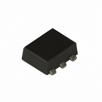
UPC8204TK-A CEL, UPC8204TK-A Datasheet - Page 3

UPC8204TK-A
Manufacturer Part Number
UPC8204TK-A
Description
IC AMP VAR GAIN 6-MINIMOLD
Manufacturer
CEL
Type
RF IC'sr
Datasheet
1.UPC8204TK-A.pdf
(35 pages)
Specifications of UPC8204TK-A
Current - Supply
11.5mA
Frequency
800MHz ~ 2.5GHz
Gain
14.5dB
Noise Figure
7.5dB
Package / Case
6-MINIMOLD
Rf Type
PHS, WLAN
Test Frequency
1.9GHz
Voltage - Supply
2.7V ~ 3.3V
Mounting Style
SMD/SMT
Operating Frequency
2.5 GHz
Operating Supply Voltage
2.7 V to 3.3 V
Lead Free Status / RoHS Status
Lead free / RoHS Compliant
P1db
-
Lead Free Status / Rohs Status
Lead free / RoHS Compliant
1.
2.
3.
4.
5.
6.
7.
8.
9.
5. 1
5. 2
6. 1
6. 2
6. 3
PIN EXPLANATION...............................................................................................................................................4
ABSOLUTE MAXIMUM RATINGS .......................................................................................................................5
RECOMMENDED OPERATING RANGE .............................................................................................................5
ELECTRICAL CHARACTERISTICS .....................................................................................................................5
TEST CIRCUITS ....................................................................................................................................................6
TYPICAL CHARACTERISTICS.............................................................................................................................8
PACKAGE DIMENSIONS.................................................................................................................................... 31
NOTES ON CORRECT USE ............................................................................................................................. 32
RECOMMENDED SOLDERING CONDITIONS ................................................................................................. 32
5. 1. 1
5. 1. 2
5. 1. 3
5. 2. 1
5. 2. 2
5. 2. 3
f = 1.9 GHz...................................................................................................................................................6
f = 2.4 GHz...................................................................................................................................................7
Inductor loading with external bias tee at output port ...................................................................................9
Output port matching at f = 1.9 GHz .......................................................................................................... 10
Output port matching at f = 2.4 GHz .......................................................................................................... 22
Test circuit 1..................................................................................................................................6
Illustration of the test circuit 1 assembled on evaluation board .....................................................6
Component list ..............................................................................................................................6
Test circuit 2..................................................................................................................................7
Illustration of the test circuit 2 assembled on evaluation board .....................................................7
Component list ..............................................................................................................................7
Data Sheet PU10408EJ02V0DS
CONTENTS
µ
PC8204TK
3


