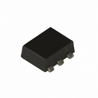
UPC8204TK-A CEL, UPC8204TK-A Datasheet - Page 4

UPC8204TK-A
Manufacturer Part Number
UPC8204TK-A
Description
IC AMP VAR GAIN 6-MINIMOLD
Manufacturer
CEL
Type
RF IC'sr
Datasheet
1.UPC8204TK-A.pdf
(35 pages)
Specifications of UPC8204TK-A
Current - Supply
11.5mA
Frequency
800MHz ~ 2.5GHz
Gain
14.5dB
Noise Figure
7.5dB
Package / Case
6-MINIMOLD
Rf Type
PHS, WLAN
Test Frequency
1.9GHz
Voltage - Supply
2.7V ~ 3.3V
Mounting Style
SMD/SMT
Operating Frequency
2.5 GHz
Operating Supply Voltage
2.7 V to 3.3 V
Lead Free Status / RoHS Status
Lead free / RoHS Compliant
P1db
-
Lead Free Status / Rohs Status
Lead free / RoHS Compliant
1.
4
Pin
No.
Note Pin voltage is measured at V
1
2
3
4
5
6
PIN EXPLANATION
OUTPUT
INPUT
Name
GND
V
Pin
V
AGC
CC
Voltage
as same
as V
through
external
inductor
2.7 to 3.3
Voltage
Applied
0 to 3.3
(V)
CC
−
0
Voltage
(V)
Pin
1.2
−
−
−
−
Note
CC
= 3.0 V
RF input pin.
This pin should be coupled with
capacitor (example 100 pF) for DC
cut. Input return loss can be
improved with external impedance
matching circuit.
Ground pin.
This pin should be connected to
system ground with minimum
inductance. Ground pa- ttern on
the board should be formed as
wide as possible. Ground pins
must be connected together with
wide ground pattern to decrease
impedance difference.
RF output pin.
This pin is de-signed as open
collector of high impedance. This
pin must be externally equipped
with matching circuits.
Supply voltage pin.
This pin must be equipped with
bypass capacitor (example 1 000
pF) to minimize its RF impedance.
Gain control pin.
Data Sheet PU10408EJ02V0DS
Function and Applications
Control
circuit
6
Internal Equivalent Circuit
⎯⎯⎯
Control
circuit
µ
3
GND
PC8204TK
Bias
circuit
5
4
1
2
5
2


