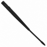
0600-00024 Laird Technologies, 0600-00024 Datasheet - Page 21

0600-00024
Manufacturer Part Number
0600-00024
Description
ANTENNA 915MHZ 1/2WV 7" RA RPSMA
Manufacturer
Laird Technologies
Specifications of 0600-00024
Antenna Type
Whip: 1/2 Wave, Swivel, Tilt (Right Angle)
Number Of Bands
1
Frequency
902MHz ~ 928MHz
Vswr
2
Gain
2dBi
Termination
RP-SMA
Mounting Type
Connector
Height (max)
8.25" (209.5mm)
Impedance
50 Ohms
Technology Type
1/2 Wave Wireless Transceiver Antenna
Termination Style
RPSMA
Lead Free Status / RoHS Status
Lead free / RoHS Compliant
Lead Free Status / RoHS Status
Lead free / RoHS Compliant, Lead free / RoHS Compliant
RSSI (pin 13)
Instantaneous RSSI
Received Signal Strength Indicator is used by the OEM Host as an indication of instantaneous signal strength at the
receiver. The OEM Host must calibrate RSSI without an RF signal being presented to the receiver. Calibration is
accomplished by following the steps listed below.
1) Power up only one transceiver in the coverage area.
2) Measure the RSSI signal to obtain the minimum value with no other signal present.
3) Power up another transceiver and begin sending data from that transceiver to the transceiver being measured. Make
sure the two transceivers are separated by approximately ten feet.
4) Measure the peak RSSI, while the transceiver is in Session, to obtain a maximum value at full signal strength.
Validated RSSI
As RSSI is only valid when the
local transceiver is receiving an RF
packet from a remote transceiver,
instantaneous RSSI can be very
tricky to use.
transceiver stores the most recent
valid RSSI value. The OEM Host
issues the
command to request that value
(details can be found in the
the-Fly
Reference
RSSI
Receive Packet and Send Data
Complete API commands and
from
Validated RSSI is not available at
the RSSI pin.
equation approximates the RSSI curve:
UP_Reset (pin 15)
UP_Reset provides a direct connection to the reset pin
on the AC4790 microprocessor and is used to force a
soft reset. For a valid reset, reset must be asserted
High for a minimum of 10ms.
Command/Data (pin 17)
When logic High, the transceiver interprets incoming
OEM Host data as transmit data to be sent to other
transceivers and their OEM Hosts. When logic Low, the
transceiver interprets OEM Host data as command
data.
can
the
). Additionally, validated
Report Last Good RSSI
Control
be
Probe
obtained
Therefore, the
The following
command.
Command
Signal Strength (dBm) =
from
On-
1.2
0.8
0.6
0.4
0.2
1
0
-105
-100
Figure 8 - RSSI Voltage vs. Received Signal Strength
(
-95
-46.9
∗
-90
V
AD In (pin 18)
AD In can be used as a cost savings to replace Analog-
to-Digital converter hardware. Reading of this pin
can be performed locally using the Read ADC
command found in the
Reference
Session Status (pin 20)
Reports logic Low during a Session and logic High
when not in Session. The inverse of this pin can be
obtained from pin GO0 when Protocol Status is
enabled.
RSSI
-85
)
-
Signal at Receiver (dBm)
.
53.9
-80
(4)
-75
On-the-Fly Control Command
-70
-65
-60
-55
21
-50


