0600-00024 Laird Technologies, 0600-00024 Datasheet - Page 30
0600-00024
Manufacturer Part Number
0600-00024
Description
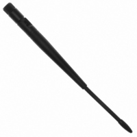
ANTENNA 915MHZ 1/2WV 7" RA RPSMA
Manufacturer
Laird Technologies
Specifications of 0600-00024
Antenna Type
Whip: 1/2 Wave, Swivel, Tilt (Right Angle)
Number Of Bands
1
Frequency
902MHz ~ 928MHz
Vswr
2
Gain
2dBi
Termination
RP-SMA
Mounting Type
Connector
Height (max)
8.25" (209.5mm)
Impedance
50 Ohms
Technology Type
1/2 Wave Wireless Transceiver Antenna
Termination Style
RPSMA
Lead Free Status / RoHS Status
Lead free / RoHS Compliant
Lead Free Status / RoHS Status
Lead free / RoHS Compliant, Lead free / RoHS Compliant


Interface Timeout
Protocol Status
RF Packet Size
Session Count
Destination ID
Original Max
API Control
Max Power
RS-485 DE
Parameter
Product ID
System ID
CTS On
CTS Off
MAC ID
Refresh
Power
Parity
EEPROM
Address
0x5B
0x5C
0x5D
0xC1
0xC2
0xC4
0x58
0x63
0x6F
0x70
0x76
0x7F
0x80
0x8E
0x90
(Bytes)
Length
15
1
1
1
1
1
1
6
1
1
6
1
1
1
1
Range
0x02 –
0x01 –
0x01 –
0x00 –
0x00 –
0x00 –
0x00 –
0x00 –
0xE3,
0xE3,
0xFE
0xFF
0x80
0xFF
0x60
0xFF
0xFF
0xFF
0xFF
0xFF
-
FF, FF, FF, FF, FF, 0xFF Specifies destination for RF packets.
Set in production and
Set in production and
00010000 (0x10)
can vary
can vary
Default
0xAC
0xD2
0xFF
0xFF
0xE3
0x04
0x80
0x01
0x08
Specifies a byte gap timeout, used in conjunction with RF
Packet Size to determine, when a packet coming over the
interface is complete (0.5ms per increment).
Used in conjunction with Interface Timeout, specifies the
maximum size of an RF packet.
CTS will be deasserted (High) when the transmit buffer
contains at least this many characters.
Once CTS has been deasserted, CTS will be reasserted
(Low) when the transmit buffer contains this many or less
characters.
Used to increase or decrease transmit power output. The
transceivers are shipped at maximum allowable power.
0xE3 = Enable Parity
0xFF = Disable Parity
Note: Enabling Parity cuts throughput in half and the
Interface Buffer size in half.
Similar to a network password. Radios must have the same
system ID to communicate with each other.
0xE3 = GO0 is active Low DE for control of external RS-485
hardware.
0xFF = Disable RS-485 DE
Factory programmed unique IEEE MAC Address.
Copy of original Max Power EEPROM setting. This address
may be modified but should not be modified.
Bytes 0x90 – 0x93: Product ID - 4490, 4486, 4868, 4790
Bytes 0x94-95: Prefix - CL, CN or AC
Bytes 0x96-0x99: Power - 200M, 200A, 1000, 1x1.
Note: there will be a period in front of the 1x1 to keep the
field at four bytes.
0x9A – 0x9C: Interface - 232, 485, TTL.
0x9D – 0x9E: Setup script; 01 is stock
0x9F: Reserved for future use; always 0xFF
Settings are:
bit-7 – Broadcast Packets
0 = Addressed Packets
1 = Broadcast Packets
bit-6 – Probe
0 = Disable Probe
1 = Enable Probe
bit-5 – SLock1
0 = Disable
1 = Enable
bit-4 – SLock0
bit-3 – Unicast Packets
bit-2 – Send Data Complete Enable
bit-1 – API Transmit Packet Enable
bit-0 – API Receive Packet Enable
Determines if the GO0 and GO1 serve as generic output or
serve as the protocol status.
This byte specifies the number of hops a transceiver stays in
Session with another transceiver
0 = Disable
1 = Enable
0 = Broadcast or Addressed Packets
1 = Addressed Packets only
0 = Disable
0 = Disable Transmit API Packet
1 = Enable Transmit API Packet
0 = Disable Receive API Packet
1 = Enable Receive API Packet
1 = Enable
Description
30
Related parts for 0600-00024
Image
Part Number
Description
Manufacturer
Datasheet
Request
R

Part Number:
Description:
CIRCUIT PIN PRINTED .250"
Manufacturer:
Mill-Max Manufacturing Corp.
Datasheet:
Part Number:
Description:
CIRCUIT PIN PRINTED .250"
Manufacturer:
Mill-Max Manufacturing Corp.
Datasheet:
Part Number:
Description:
CIRCUIT PIN PRINTED .250"
Manufacturer:
Mill-Max Manufacturing Corp.
Datasheet:
Part Number:
Description:
CIRCUIT PIN PRINTED .250"
Manufacturer:
Mill-Max Manufacturing Corp.
Datasheet:

Part Number:
Description:
ANT 2.4GHZ 1/2 WAVE 5" RA U.FL
Manufacturer:
Laird Technologies

Part Number:
Description:
ANTENNA 2.45GHZ 7" RA U.FL PLUG
Manufacturer:
Laird Technologies

Part Number:
Description:
ANTENNA 915MHZ 1/2WV 6" RA RPSMA
Manufacturer:
Laird Technologies
Datasheet:

Part Number:
Description:
ANTENNA 2.4GHZ 5/8WV RA 7" RPSMA
Manufacturer:
Laird Technologies

Part Number:
Description:
ANTENNA 915MHZ 1/2WAVE 7"RA MMCX
Manufacturer:
Laird Technologies
Datasheet:

Part Number:
Description:
ANTENNA 2.4GHZ 1/2WAVE RA 5"MMCX
Manufacturer:
Laird Technologies

Part Number:
Description:
BLUETOOTH EVAL BOARD BTM511
Manufacturer:
Laird Technologies
Datasheet:

Part Number:
Description:
Bluetooth / 802.15.1 Modules & Development Tools BLUETTH Multimed MODLE, No ANT DEVKIT
Manufacturer:
Laird Technologies
Datasheet:

Part Number:
Description:
Bluetooth Serial Module Development Kit
Manufacturer:
Laird Technologies