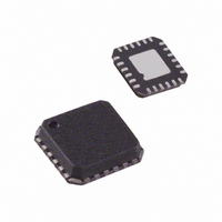
ADL5382ACPZ-R7 Analog Devices Inc, ADL5382ACPZ-R7 Datasheet - Page 3

ADL5382ACPZ-R7
Manufacturer Part Number
ADL5382ACPZ-R7
Description
IC DEMOD QUAD 700M2.7GHZ 24LFCSP
Manufacturer
Analog Devices Inc
Datasheet
1.ADL5382ACPZ-R7.pdf
(28 pages)
Specifications of ADL5382ACPZ-R7
Design Resources
Interfacing ADL5382 to AD9262 as an RF-to-Bits Solution (CN0062)
Function
Demodulator
Lo Frequency
700MHz ~ 2.7GHz
Rf Frequency
700MHz ~ 2.7GHz
P1db
14.5dBm
Gain
3.3dB
Noise Figure
17.6dB
Current - Supply
220mA
Voltage - Supply
4.75 V ~ 5.25 V
Package / Case
24-VFQFN, 24-CSP Exposed Pad
Frequency Range
700MHz To 2.7GHz
Rf Type
Quadrature
Supply Voltage Range
4.75V To 5.25V
Rf Ic Case Style
LFCSP
No. Of Pins
24
Operating Temperature Range
-40°C To +85°C
Lead Free Status / RoHS Status
Lead free / RoHS Compliant
Other names
ADL5382ACPZ-R7TR
Available stocks
Company
Part Number
Manufacturer
Quantity
Price
Company:
Part Number:
ADL5382ACPZ-R7
Manufacturer:
Analog Devices Inc
Quantity:
1 881
Part Number:
ADL5382ACPZ-R7
Manufacturer:
ADI/亚德诺
Quantity:
20 000
SPECIFICATIONS
V
differentially loaded with 450 Ω. Loss of the balun used to drive the RF port was de-embedded from these measurements.
Table 1.
Parameter
OPERATING CONDITIONS
LO INPUT
I/Q BASEBAND OUTPUTS
POWER SUPPLIES
DYNAMIC PERFORMANCE at RF = 900 MHz
DYNAMIC PERFORMANCE at RF = 1900 MHz
S
LO and RF Frequency Range
Input Return Loss
LO Input Level
Voltage Conversion Gain
Demodulation Bandwidth
Quadrature Phase Error
I/Q Amplitude Imbalance
Output DC Offset (Differential)
Output Common Mode
0.1 dB Gain Flatness
Output Swing
Peak Output Current
Voltage
Current
Conversion Gain
Input P1dB
Second-Order Input Intercept (IIP2)
Third-Order Input Intercept (IIP3)
LO to RF
RF to LO
IQ Magnitude Imbalance
IQ Phase Imbalance
LO to IQ
Noise Figure
Noise Figure under Blocking Conditions
Conversion Gain
Input P1dB
Second-Order Input Intercept (IIP2)
Third-Order Input Intercept (IIP3)
LO to RF
RF to LO
IQ Magnitude Imbalance
IQ Phase Imbalance
LO to IQ
Noise Figure
Noise Figure under Blocking Conditions
= 5 V, T
A
= 25°C, f
LO
= 900 MHz, f
IF
= 4.5 MHz, P
Condition
LOIP, LOIN
LO driven differentially through a balun at 900 MHz
QHI, QLO, IHI, ILO
450 Ω differential load on I and Q outputs at 900 MHz
200 Ω differential load on I and Q outputs at 900 MHz
1 V p-p signal, 3 dB bandwidth
At 900 MHz
0 dBm LO input at 900 MHz
Differential 200 Ω load
Each pin
VPA, VPL, VPB, VPX
BIAS pin open
R
−5 dBm each input tone
−5 dBm each input tone
RFIN, RFIP terminated in 50 Ω
LOIN, LOIP terminated in 50 Ω
RFIN, RFIP terminated in 50 Ω
With a −5 dBm interferer 5 MHz away
−5 dBm each input tone
−5 dBm each input tone
RFIN, RFIP terminated in 50 Ω
LOIN, LOIP terminated in 50 Ω
RFIN, RFIP terminated in 50 Ω
With a −5 dBm interferer 5 MHz away
BIAS
= 4 kΩ
LO
= 0 dBm, BIAS pin open, Z
Rev. 0 | Page 3 of 28
O
= 50 Ω, unless otherwise noted. Baseband outputs
Min
0.7
−6
4.75
Typ
−11
0
3.9
3.0
370
0.2
0.05
±5
VPOS − 2.8
50
2
12
220
196
3.9
14.7
73
33.5
−92
−89
0.05
0.2
−43
14.0
19.9
3.9
14.4
65
30.5
−71
−78
0.05
0.2
−41
15.6
20.5
Max
2.7
+6
5.25
ADL5382
Unit
GHz
dB
dBm
dB
dB
MHz
Degrees
dB
mV
V
MHz
V p-p
mA
V
mA
mA
dB
dBm
dBm
dBm
dBm
dBc
dB
Degrees
dBm
dB
dB
dB
dBm
dBm
dBm
dBm
dBc
dB
Degrees
dBm
dB
dB


