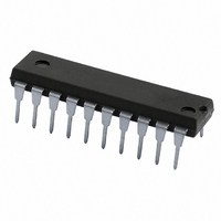
TDA9801/V1,112 NXP Semiconductors, TDA9801/V1,112 Datasheet - Page 8

TDA9801/V1,112
Manufacturer Part Number
TDA9801/V1,112
Description
IC PLL DEMODULATOR 20-DIP
Manufacturer
NXP Semiconductors
Datasheet
1.TDA9801V1112.pdf
(32 pages)
Specifications of TDA9801/V1,112
Package / Case
20-DIP (0.300", 7.62mm)
Function
Demodulator, Detector
Current - Supply
70mA
Voltage - Supply
4.5 V ~ 9.9 V
Mounting Style
Through Hole
Lead Free Status / RoHS Status
Lead free / RoHS Compliant
Gain
-
Noise Figure
-
P1db
-
Lo Frequency
-
Rf Frequency
-
Lead Free Status / RoHS Status
Lead free / RoHS Compliant, Lead free / RoHS Compliant
Other names
935260644112
TDA9801N
TDA9801N
TDA9801N
TDA9801N
Philips Semiconductors
1999 Aug 26
G
B
R
C
VCO and video demodulator; note 3
f
V
f
t
V
I
Video amplifier output (sound carrier off): pin VSO
V
V
V
V
V
R
I
VCO(max)
cr(PC)
acq
offset(TPLL)
bias
V
f
IF( 3dB)
VCO(rms)
i(sens)(VIF)(rms)
o(VSO)(p-p)
sync
v(clu)
v(cll)
o(intc)(rms)
i(dif)
i(dif)
o
Single standard VIF-PLL demodulator
and FM-PLL detector
IF
VCO
int
SYMBOL
/ T
internal IF amplitude
difference between picture
and sound carrier
IF gain control
differential input resistance
differential input
capacitance
maximum VCO frequency
VCO frequency variation
with temperature
VCO voltage swing
(RMS value)
picture carrier capture
frequency range
acquisition time
sensitivity of VIF input
(RMS value)
offset current at pin TPLL
VSO output voltage
(peak-to-peak value)
sync pulse voltage level
upper video clipping
voltage level
lower video clipping voltage
level
intercarrier output voltage
(RMS value)
output resistance
DC bias current
3 dB IF bandwidth
PARAMETER
within AGC range
see Fig.6
upper limit cut-off
frequency
note 2
note 2
for carrier regeneration;
f = 2f
free running; I
note 4
measured between
pins VCO1 and VCO2
negative
positive
BL = 60 kHz; note 5
PLL still locked;
maximum IF gain; note 6
C/N = 10 dB; note 7
note 8
see Fig.5
sound carrier on; note 9
note 2
for internal emitter-follower
at pin VSO
f
f
f
f
f
V
V
PC
PC
PC
PC
PC
P
P
PC
= 5 V
= 9 V
= 38.9 MHz
= 45.75 MHz
= 58.75 MHz
= 38.9 or 45.75 MHz
= 58.75 MHz
CONDITIONS
8
AFC
= 0;
64
62
70
1.7
1.2
125
1.4
1.4
0.90
0.95
1.35
V
1.8
P
MIN.
1.1 V
0.7
70
68
100
2.2
1.7
130
120
100
80
1.8
1.8
50
100
1.0
1.1
1.5
0.7
32
2.5
P
TYP.
1
1
2.7
2.5
30
90
140
1.25
1.25
1.6
0.9
10
Product specification
20
2.0
MAX.
TDA9801
10
6
dB
dB
dB
MHz
k
pF
MHz
K
mV
mV
mV
MHz
MHz
ms
V
V
V
V
V
mV
mA
V
V
A
UNIT
1


