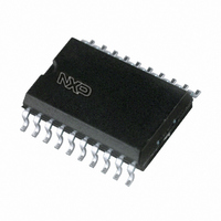
TDA9801T/V1,118 NXP Semiconductors, TDA9801T/V1,118 Datasheet - Page 14

TDA9801T/V1,118
Manufacturer Part Number
TDA9801T/V1,118
Description
IC PLL DEMODULATOR 20-SOIC
Manufacturer
NXP Semiconductors
Datasheet
1.TDA9801V1112.pdf
(32 pages)
Specifications of TDA9801T/V1,118
Package / Case
20-SOIC (0.300", 7.50mm Width)
Function
Demodulator, Detector
Current - Supply
70mA
Voltage - Supply
4.5 V ~ 9.9 V
Mounting Style
SMD/SMT
Lead Free Status / RoHS Status
Lead free / RoHS Compliant
Gain
-
Noise Figure
-
P1db
-
Lo Frequency
-
Rf Frequency
-
Lead Free Status / RoHS Status
Lead free / RoHS Compliant, Lead free / RoHS Compliant
Other names
935260645118
TDA9801TD-T
TDA9801TD-T
TDA9801TD-T
TDA9801TD-T
Philips Semiconductors
10. Measurements taken with SAW filter G1962; VSB modulation; f
11. The 7 dB buffer amplifier gain accounts for 1 dB loss in the sound trap. The buffer output signal is typical 2 V (p-p).
12. The leakage current of C
13. S/N is the ratio of the black-to-white amplitude to the black level noise voltage (RMS value) at pin CVBS.
14. The intermodulation figures are defined:
15. To match the AFC output signal to different tuning systems a current source output is provided (see Fig.8).
16. The no mute state is also valid when pin MUTE is not connected.
17. The input signal is provided by an external generator with 50
18. To allow a higher frequency deviation, the value of resistor R3 on pin DAF (see Fig.13) has to be increased.
19. The leakage current of the 2.2 F decoupling capacitor should not exceed 100 nA.
20. For all S/N measurements the used vision IF modulator has to meet the following specifications:
21. Input signal according to B/G standard of Table 1:
Table 1 Input frequencies and carrier ratios
1999 Aug 26
f
f
PC/SC
PC
SC
Single standard VIF-PLL demodulator
and FM-PLL detector
SYMBOL
If no sound trap is applied a resistor of 330
B = 5 MHz weighted in accordance with “CCIR 567” at a source impedance of 50 .
a)
b)
capacitor, f
Pin AGC has to be connected to the supply voltage. Measurements are taken at 50 s de-emphasis (75 s at the
M standard).
However, the AF output signal must not exceed 0.5 V (nominal value) for THD = 0.2%. R3 = 4.7 k provides 6 dB
amplification.
a) Incidental phase modulation for black-to-white jump less than 0.5 degrees
b) AF performance, measured with the television demodulator AMF2 (audio output, weighted S/N ratio), better than
a) Input: V
b) Reference: FM deviation = 27 kHz and measurements are taken at 50 s de-emphasis.
60 dB (deviation 27 kHz) for white picture video modulation.
IM(0.92/1.1)
IM(2.76/3.3
IM 0.92 1.1
IM 2.76 3.3
mod
i(VIF)(rms)
) value at 2.76 (or 3.3) MHz referenced to colour carrier.
picture carrier frequency
sound carrier frequency
picture-to-sound carrier ratio
value at 0.92 (or 1.1) MHz referenced to black or white signal
= 1 kHz and 27 kHz (54% FM deviation) of audio reference. A VIF input signal is not permitted.
=
=
20
20
= 10 mV, VSB modulation and 10% residual carrier
DESCRIPTION
log
log
AGC
V
------------------------------------------------------ -
V
V
------------------------------------------------------ -
V
o
o
o
o
should not exceed 1 A. Larger currents will increase the tilt.
at 4.4 (3.58) MHz
at 0.92 (1.1) MHz
at 4.4 (3.58) MHz
at 2.76 (3.3) MHz
must be connected between pins VSO and VI.
+
3.6 dB
38.9
33.4
B/G
13
14
video
source impedance, AC-coupled with a 10 nF
STANDARD
> 0.5 MHz; loop bandwidth BL = 60 kHz.
45.75
41.25
M/N
7
58.75
54.25
M
7
Product specification
TDA9801
UNIT
MHz
MHz
dB


