AMMC-6120-W50 Avago Technologies US Inc., AMMC-6120-W50 Datasheet
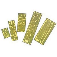
IC MMIC FREQ MULTIPLIER 6-20GHZ

AMMC-6120-W50

Manufacturer Part Number
AMMC-6120-W50
Description
IC MMIC FREQ MULTIPLIER 6-20GHZ
Manufacturer
Avago Technologies US Inc.
Datasheet

Specifications of AMMC-6120-W50

Function
Frequency Multiplier
Supply Current
85mA
Supply Voltage Range
5V
Frequency Max
10GHz
Frequency Min
4GHz
Supply Voltage Max
7V
Gain
1dB
Manufacturer's Type
MMIC Amplifier
Number Of Channels
1
Frequency (max)
20GHz
Operating Supply Voltage (typ)
5V
Package Type
Chip
Mounting
Surface Mount
Lead Free Status / RoHS Status
Lead free / RoHS Compliant
Lead Free Status / RoHS Status
Lead free / RoHS Compliant, Lead free / RoHS Compliant

Available stocks

Company
Part Number
Manufacturer
Quantity
Price
Part Number:
AMMC-6120-W50
Manufacturer:
AVAGO/安华高
Quantity:
20 000
AMMC-6120
8-20 GHz Output x2
Active Frequency Multiplier
Data Sheet
Description
Avago Technologies' AMMC-6120 is an easy-to-use x2
active frequency multiplier MMIC designed for com-
mercial communication systems. Though capable of
doubling to 24 GHz with reduced fundamental suppres-
sion, the MMIC is designed to take a 4 to 10 GHz input
and double it to 8 to 20 GHz. It has integrated output
amplifier, matching harmonic suppression, and bias
networks. The input/output are matched to 50 Ω
and fully DC blocked. The MMIC is fabricated using
PHEMT technology. The backside of this die is both RF
and DC ground. This helps simplify the assembly process
and reduces assembly related performance variations
and costs. For improved reliability and moisture protec-
tion, the die is passivated at the active areas. This MMIC is
a cost effective alternative to bulky hybrid FET and diode
doublers that require high input drive power, have high
C.L. and poor fundamental suppression.
AMMC-6120 Absolute Maximum Ratings
Symbol Parameters/Conditions
V
V
I
P
T
T
T
Note:
1. Operation in excess of any one of these conditions may result in
d
ch
stg
max
d
in
g
permanent damage to this device.
Positive Drain Voltage
Gate Supply Voltage
Drain Current
CW Input Power
Operating Channel Temp.
Storage Case Temp.
Maximum Assembly Temp.
(60 sec. max.)
[1]
Units
V
V
mA
dBm
°C
°C
°C
Min.
-3.0
-65
Max.
7
0.5
120
15
+150
+150
+300
Features
• Input frequency range: 4-10 GHz
• Broad input power range: -11 to +5 dBm
• Output power: +14 dBm (Pin = +3 dBm)
• Fundamental Suppression of 25 dBc
• 50 Ω input and output match
• Supply bias of -1.4 V, 5 V and 85 mA
Applications
• Microwave radio systems
• Satellite VSAT, DBS Up/Down Link
• LMDS & Pt-Pt mmW Long Haul
• Broadband Wireless Access
• WLL and MMDS loops
(including 802.16 and 802.20 WiMax)
Chip Size: 1600 x 1000 µm (64 x 40 mils)
Chip Size Tolerance: ± 10 µm (± 0.4 mils)
Chip Thickness: 100 ± 10 µm (4 ± 0.4 mils)
Pad Dimensions: 120 x 80 µm (5x3 ± 0.4 mils)
Attention: Observe precautions for
handling electrostatic sensitive devices.
Refer to Avago Application Note A004R:
Electrostatic Discharge Damage and Control.
ESD Machine Model (Class A)
ESD Human Body Model (Class 0)

Related parts for AMMC-6120-W50

AMMC-6120-W50 Summary of contents

Page 1

... AMMC-6120 8-20 GHz Output x2 Active Frequency Multiplier Data Sheet Description Avago Technologies' AMMC-6120 is an easy-to-use x2 active frequency multiplier MMIC designed for com- mercial communication systems. Though capable of doubling to 24 GHz with reduced fundamental suppres- sion, the MMIC is designed to take GHz input and double GHz ...

Page 2

... AMMC-6120 DC Specifications/Physical Properties Symbol Parameters and Test Conditions I Drain Supply Current dq V Gate Supply Operating Voltage g q [2] Thermal Resistance ch-b (Backside Temperature, T Notes: 1. Ambient operational temperature T = 25°C unless otherwise noted Channel-to-backside Thermal Resistance (q backside temperature ( 25°C calculated from measured data. ...

Page 3

... AMMC-6120 Typical Performances (T = 25° mA Note: These measurements are test environment. Aspects of the amplifier performance may be improved over a narrower bandwidth by application of additional conjugate, linearity or low noise (Gopt) matching -10 -15 -20 -25 - Output Frequency (GHz) Figure 1. Output Power vs. Output Freq. @ Pin=+3dBm 19 18 ...

Page 4

Fout=8GHz Vg=-1.2V, Vd=4.5V 4 Vg=-1.2V, Vd=5.0V Vg=-1.4V, Vd=4.5V 2 Vg=-1.4V, Vd=5. Input Power [1H] (dBm) Figure 7. 2H Output Power Vs Input Power @ ...

Page 5

Fout=16GHz Vg=-1.2V, Vd=4.5V 4 Vg=-1.2V, Vd=5.0V Vg=-1.4V, Vd=4.5V 2 Vg=-1.4V, Vd=5. Input Power [1H] (dBm) Figure 13. 2H Output Power Vs Input Power @ ...

Page 6

... AMMC-6120 is biased with a single positive drain supply and single negative gate supply using separate bypass capacitors normally biased with the drain supply connected to both the VdAB and the Vdd bond pads and the gate supply connected to the VgD bond pad ...

Page 7

... VdAB VgD RFin Figure 23. AMMC-6120 simplified schematic. 7 Thermosonic wedge bonding is the preferred method for wire attachment to the bond pads. Gold mesh can be attached using a 2 mil round tracking tool and a tool force of approximately 22 grams and a ultrasonic power of roughly 55 dB for a duration of 76 ± ...

Page 8

... Figure 25. AMMC-6120 assembly diagram. Ordering Information: AMMC-6120-W10 = 10 devices per tray AMMC-6120-W50 = 50 devices per tray For product information and a complete list of distributors, please go to our website: Avago, Avago Technologies, and the A logo are trademarks of Avago Technologies in the United States and other countries. ...

Related keywords