AMMC-6140-W10 Avago Technologies US Inc., AMMC-6140-W10 Datasheet
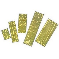
IC MMIC FREQ MULT DUAL 20-40GHZ

AMMC-6140-W10

Manufacturer Part Number
AMMC-6140-W10
Description
IC MMIC FREQ MULT DUAL 20-40GHZ
Manufacturer
Avago Technologies US Inc.
Datasheet

Specifications of AMMC-6140-W10

Function
Frequency Multiplier
Supply Current
27mA
Supply Voltage Range
4.5V
Frequency Max
20GHz
Frequency Min
10GHz
Supply Voltage Max
7V
Gain
1dB
Lead Free Status / RoHS Status
Lead free / RoHS Compliant

Available stocks

Company
Part Number
Manufacturer
Quantity
Price
Part Number:
AMMC-6140-W10
Manufacturer:
AVAGO
Quantity:
5 000
Part Number:
AMMC-6140-W10
Manufacturer:
AVAGO/安华高
Quantity:
20 000
AMMC-6140
20 – 40 GHz Output x2 Active Frequency Multiplier
Data Sheet
Description
Avago’s AMMC-6140 is an easy­-to-use x2 active frequency­
multiplier MMIC designed for commercial communica-
tion sy­stems. The MMIC takes a 10 to 20 GHz input signal
and doubles it to 20 to 40 GHz. It could also be used
between 9–10 GHz and 20–22 GHz with slight degrada-
tion in Conversion Loss or Fundamental Suppression. It
has an integrated matching, harmonic suppression, and
bias network. The input/output are matched to 50Ω and
fully­ DC blocked. The MMIC is fabricated using PHEMT
technology­. The backside of this die is both RF and DC
ground. This helps simplify­ the assembly­ process and
reduces assembly­-related performance variations and
costs. For improved reliability­ and moisture protection,
the die is passivated at the active areas. This MMIC is a
cost effective alternative to bulky­ hy­brid FET and diode
doublers that require high input drive levels, have high
conversion loss and poor fundamental suppression.
Absolute Maximum Ratings
Symbol Parameters/Conditions
V
V
I
P
T
T
T
Note:
1. Operation in excess of any­ one of these conditions may­ result in
d
ch
stg
in
max
d
g
permanent damage to this device.
Positive Drain Voltage
Gate Supply­ Voltage
Drain Current
CW Input Power
Operating Channel Temperature
Storage Case Temperature
Maximum Assembly­ Temp
(60 sec max)
[1]
Units
V
V
mA
dBm
°C
°C
°C
Min.
-3.0
-65
Max.
7
0.5
-3
15
+150
+150
+300
Features
• Input frequency­ range: 10–20 GHz
• Broad input power range: -9 to +7 dBm
• Output power: -1 to 0 dBm (Pin = +4dB)
• Fundamental suppression of 25 dBc
• 50Ω input and output match
• Supply­ bias of -1.2V, 4.5V and 27 mA
Applications
• Microwave radio sy­stems
• Satellite VSAT, DBS Up/Down Link
• LMDS & Pt-Pt mmW Long Haul
• Broadband Wireless Access
• WLL and MMDS loops
(including 802.16 and 802.20 WiMax)
Chip Size:
Chip Size Tolerance:
Chip Thickness:
Pad Dimensions:
Attention: Observe precautions for
handling electrostatic sensitive devices.
ESD Machine Model (Class A)
ESD Human Body Model (Class 0)
Refer to Avago Application Note A004R:
Electrostatic Discharge Damage and Control.
1300 x 900 µm (51 x 35 mils)
±10 µm (±0.4 mils)
100 ± 10 µm (4 ± 0.4 mils)
120 x 80 µm (5x3 ± 0.4 mils)

Related parts for AMMC-6140-W10

AMMC-6140-W10 Summary of contents

Page 1

... AMMC-6140 20 – 40 GHz Output x2 Active Frequency Multiplier Data Sheet Description Avago’s AMMC-6140 is an easy­-to-use x2 active frequency­ multiplier MMIC designed for commercial communica- tion sy­stems. The MMIC takes GHz input signal and doubles GHz. It could also be used between 9–10 GHz and 20–22 GHz with slight degrada- tion in Conversion Loss or Fundamental Suppression ...

Page 2

... AMMC-6140 DC Specifications/Physical Properties Symbol Parameters and Test Conditions I Drain Supply­ Current (under any­ RF power drive and temperature Gate Supply­ Operating Voltage g θ Thermal Resistance (Backside Temp. T [2] ch-b Notes: 1. Ambient operational temperature T = 25°C unless otherwise noted Channel-to-backside Thermal Resistance (θ ...

Page 3

... AMMC-6140 Typical Performances (T = 25° NOTE: These measurements are in a 50Ω test environment. Aspects of the multiplier performance may­ be improved over a narrower bandwidth by­ application of additional conjugate, linearity­, or low noise (Γopt) matching O/P Freq=2*Fin -10 Fundamental 3H -15 4H -20 -25 -30 -35 -40 -45 16 ...

Page 4

... DC voltage is present at either port. However, the RF output port has an internal output matching circuit that presents a DC short. Proper care should be taken while biasing a sequential circuit to the AMMC-6140 as it might cause a DC short (Use a DC block if sub sequential circuit is not AC coupled). No ground wires are needed since ground connections are made with plated through-holes to the backside of the device ...

Page 5

... RFin Figure 10. AMMC-6140 simplified schematic. 0 900 620 RFI 0 0 Figure 11. AMMC-6140 Bonding Pad Locations. 5 650 1090 Vgg Vdd (Dimensions in µm) RFout 395 RFO 1300 ...

Page 6

... Figure 12. AMMC-6140 Assembly Diagram. Note: 0.1uF capacitors on gate and drain lines, not shown, required. Ordering Information AMMC-6140-W10 = 10 devices per tray­ AMMC-6140-W50 = 50 devices per tray­ For product information and a complete list of distributors, please go to our web site: Avago, Avago Technologies, and the A logo are trademarks of Avago Technologies Limited in the United States and other countries. ...

Related keywords