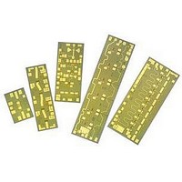
AMMC-5040-W50 Avago Technologies US Inc., AMMC-5040-W50 Datasheet - Page 10

AMMC-5040-W50
Manufacturer Part Number
AMMC-5040-W50
Description
IC MMIC AMP GAAS 20-45GHZ
Manufacturer
Avago Technologies US Inc.
Type
General Purposer
Datasheet
1.AMMC-5040-W10.pdf
(10 pages)
Specifications of AMMC-5040-W50
Function
Amplifier
Supply Current
225mA
Supply Voltage Range
2V To 5V
Frequency Max
45GHz
Frequency Min
20GHz
Supply Voltage Max
5V
Supply Voltage Min
2V
Gain
25dB
Number Of Channels
1
Frequency (max)
45GHz
Output Power
21.5@45000MHzdBm
Power Supply Requirement
Single
Single Supply Voltage (min)
2V
Single Supply Voltage (typ)
4.5V
Single Supply Voltage (max)
5V
Dual Supply Voltage (min)
Not RequiredV
Dual Supply Voltage (typ)
Not RequiredV
Dual Supply Voltage (max)
Not RequiredV
Operating Temperature Classification
Commercial
Operating Temp Range
-55C to 75C
Lead Free Status / RoHS Status
Lead free / RoHS Compliant
Lead Free Status / RoHS Status
Lead free / RoHS Compliant, Lead free / RoHS Compliant
Available stocks
Company
Part Number
Manufacturer
Quantity
Price
Part Number:
AMMC-5040-W50
Manufacturer:
AVAGO/安华高
Quantity:
20 000
Figure 15. AMMC-5040 assembly for normal amplifier applications with
single drain and single gate supply connections.
Figure 17. Separate first-stage gate and drain bias for using the AMMC-
5040 as a frequency tripler.
Ordering Information
AMMC-5040-W10 = 10 devices per tray
AMMC-5040-W50 = 50 devices per tray
For product information and a complete list of distributors, please go to our web site:
Avago, Avago Technologies, and the A logo are trademarks of Avago Technologies in the United States and other countries.
Data subject to change. Copyright © 2005-2010 Avago Technologies. All rights reserved. Obsoletes AV01-0605EN
AV02-1325EN - August 23, 2010
To V
Gate Supply
gg
Gold Plated Shim
(Optional)
DC
RFin
RFin
≥
100 pF
Cb
To V
Gate Supply
g1
To V
Drain Supply
≥
DC
100 pF
d1
DC
V
use separate V
as shown in Figure 16)
g2
Cb
To V
DC Drain Supply
to V
To V
Drain Supply
d2
g3
to V
jumper (or
DD
RFout
d4
DC
RFout
g2
bond
To V
DC Gate Supply
g2
to V
g4
www.avagotech.com
Figure 16. Separate first-stage gate bias for using the AMMC-5040 as a
frequency doubler or quadrupler. This diagram also shows an option to
the Vg
To V
Gate Supply
g1
2
DC
jumper bonding scheme used in Figure 15.
RFin
Cb
≥
100 pF
≥
100 pF
≥
100 pF
Cb
To V
Drain Supply
DD
To V
DC Gate Supply
RFout
DC
Cb
g2
to V
g4


