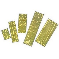
AMMC-6530-W10 Avago Technologies US Inc., AMMC-6530-W10 Datasheet - Page 8

AMMC-6530-W10
Manufacturer Part Number
AMMC-6530-W10
Description
IC MMIC IMAGE REJECT MXR 6-30GHZ
Manufacturer
Avago Technologies US Inc.
Series
AMMC-6530r
Datasheet
1.AMMC-6530-W50.pdf
(8 pages)
Specifications of AMMC-6530-W10
Function
Mixer
Noise Figure Typ
12dB
Supply Voltage Range
-1V
Frequency Max
30GHz
Frequency Min
5GHz
Supply Voltage Max
-3V
Gain
1dB
Lead Free Status / RoHS Status
Lead free / RoHS Compliant
Lead Free Status / RoHS Status
Lead free / RoHS Compliant, Lead free / RoHS Compliant
Available stocks
Company
Part Number
Manufacturer
Quantity
Price
Part Number:
AMMC-6530-W10
Manufacturer:
AVAGO/安华高
Quantity:
20 000
23. Note that all the RF input and output ports are in a
Ground-Signal-Ground configuration.
RF connections should be kept as short as reasonable
to minimize performance degradation due to undesir-
able series inductance. A single bond wire is normally
sufficient for signal connections, however double
bonding with 0.7 mil gold wire or use of gold mesh is
recommended for best performance, especially near the
high end of the frequency band. Thermosonic wedge
bonding is the preferred method for wire attachment to
the bond pads.
Gold mesh can be attached using a 2 mil round tracking
tool and a tool force of approximately 22 grams and a
ultrasonic power of roughly 55 dB for a duration of 76±8
mS. The guided wedge at an untrasonic power level of
64 dB can be used for 0.7 mil wire. The recommended
wire bond stage temperature is 150±2°C. Caution should
be taken to not exceed the Absolute Maximum Rating
for assembly temperature and time.
Figure 23. AMMC-6530 Assembly Diagram.
For product information and a complete list of distributors, please go to our web site:
Avago, Avago Technologies, and the A logo are trademarks of Avago Technologies in the United States and other countries.
Data subject to change. Copyright © 2005-2008 Avago Technologies. All rights reserved. Obsoletes 5989-3945EN
AV02-1293EN - July 30, 2008
Vg
LO/RF
IF1
Gnd
IF2
RF/LO
The chip is 100 µm thick and should be handled with
care.
This MMIC has exposed air bridges on the top surface
and should be handled by the edges or with a custom
collet (do not pick up the die with a vacuum on die
center).
This MMIC is also static sensitive and ESD precautions
should be taken.
Notes:
1. Ablebond 84-1 LM1 silver epoxy is recommended.
2. Eutectic attach is not recommended and may jeopardize reliability
Part Number Ordering Information
www.avagotech.com
of the device.
Part Number
AMMC-6530-W10
AMMC-6530-W50
Devices per Container
10
50


