DM163027-5 Microchip Technology, DM163027-5 Datasheet
DM163027-5
Specifications of DM163027-5


Related parts for DM163027-5


DM163027-5 Summary of contents
Page 1
... PICDEM™ Z Demonstration Kit © 2008 Microchip Technology Inc. User’s Guide DS51524C ...
Page 2
... PowerMate, PowerTool, REAL ICE, rfLAB, Select Mode, Total Endurance, WiperLock and ZENA are trademarks of Microchip Technology Incorporated in the U.S.A. and other countries. SQTP is a service mark of Microchip Technology Incorporated in the U.S.A. All other trademarks mentioned herein are property of their respective companies. ...
Page 3
... C.2 The PICDEM™ Z MRF24J40 2.4 GHz Daughter Card ............................... 25 C.3 Schematic .................................................................................................... 26 C.4 PCB Layout .................................................................................................. 28 C.5 PICDEM Z MRF24J40 Daughter Card Bill of Materials ............................... 33 C.6 PCB Antenna Details ................................................................................... 34 Worldwide Sales and Service .................................................................................... 38 © 2008 Microchip Technology Inc. DEMONSTRATION KIT Table of Contents ™ PICDEM Z USER’S GUIDE ...
Page 4
... PICDEM Z Demonstration Kit User’s Guide NOTES: DS51524C-page iv © 2008 Microchip Technology Inc. ...
Page 5
... Appendix B: MRF24J40MA PICDEM Z 2.4 GHz RF Board – Hardware information on the MRF24J40MA PICDEM Z 2.4 GHz RF Board. • Appendix C: PICDEM™ Z 2.4 GHz RF Card – Hardware information on the PICDEM Z 2.4 GHz RF Card. © 2008 Microchip Technology Inc. DEMONSTRATION KIT Preface NOTICE TO CUSTOMERS ™ ...
Page 6
... Optional arguments mcc18 [options] file [options] Choice of mutually exclusive errorlevel {0|1} arguments selection Replaces repeated text var_name [, var_name...] Represents code supplied by void main (void) user { ... } © 2008 Microchip Technology Inc. Examples ® IDE User’s Guide ...
Page 7
... Microchip consultant program member listing • Business of Microchip – Product selector and ordering guides, latest Microchip press releases, listing of seminars and events, listings of Microchip sales offices, distributors and factory representatives © 2008 Microchip Technology Inc. Preface DS51524C-page 3 ...
Page 8
... Local sales offices are also available to help customers. A listing of sales offices and locations is included in the back of this document. Technical support is available through the web site at: http://support.microchip.com DOCUMENT REVISION HISTORY Revision C (November 2008) • Extensive rewrite of all sections. DS51524C-page 4 ® ® © 2008 Microchip Technology Inc. ...
Page 9
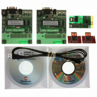
... PICDEM™ Z Motherboard • Wireless Daughter Boards • PICDEM™ Z CD-ROM 1.2 PICDEM™ Z DEMONSTRATION KIT CONTENTS The PICDEM Z Demonstration Kit (Part Number DM163027-5) contains the following items: 1. Two PICDEM™ Z Motherboards 2. Two MRF24J40MA PICDEM Z 2.4 GHz RF Boards 3. PICDEM Z CD-ROM 4. ZENA™ ...
Page 10
... It can also display a graphical representation of the network topology and the mes- sages as they flow through the network. This information can then be saved and/or exported for further analysis. Refer to the User's Guide (DS51606) for more information on the operation of the ZENA Network Analyzer. DS51524C-page 6 PICDEM™ Z DEMONSTRATION KIT © 2008 Microchip Technology Inc. ...
Page 11
... To measure the current, cut the PCB trace on the bottom side and insert an ampmeter. You can also install a low value resistor into position R9 and measure the voltage across to determine the current. © 2008 Microchip Technology Inc. Overview ® microcontrollers. The 40-pin socket (U4) ...
Page 12
... USART. The pins are connected by PCB traces. To enable or disable LED D1. The pins are connected by PCB traces. To enable or disable LED D2. The pins are connected by PCB traces. To measure current draw by all circuitry past the voltage regulator U2. PICDEM™ Z MOTHERBOARD © 2008 Microchip Technology Inc. ...
Page 13
... PICDEM™ Z CD-ROM The PICDEM Z CD-ROM contains documentation on the motherboard, wireless daughter boards, data sheets, application notes and wireless protocol software. Check the Microchip web site for the latest revisions http://www.microchip.com/wireless/. © 2008 Microchip Technology Inc. CONNECTOR J2 PINOUT J2 Signal Pin ...
Page 14
... PICDEM Z Demonstration Kit User’s Guide NOTES: DS51524C-page 10 © 2008 Microchip Technology Inc. ...
Page 15
... Please refer to the “Getting Started: Running the ZigBee-2006 Demo” document located in the directory: C:\Microchip Solutions\ZigBee2006Res\ Complete documentation is available in application note AN1232, “Microchip ZigBee-2006 Residential Stack Protocol” (DS01232). © 2008 Microchip Technology Inc. PICDEM DEMONSTRATION KIT USER’S GUIDE DS51524C-page 11 ™ ...
Page 16
... To load and run the MiWi P2P Protocol demonstration program, please refer to the “Getting Started: Running the MiWi™ P2P demo” document located in the above directory. Complete documentation is available in application note AN1204, “Microchip MiWi P2P Wireless Protocol” (DS01204). DS51524C-page 12 © 2008 Microchip Technology Inc. ...
Page 17
... The PICDEM Z motherboard schematics are shown here. The RF daughter card schematics are found in the appendices that follow. Topic included in this appendix are: • PICDEM Z Motherboard Schematics • PICDEM Z Motherboard Bill of Materials © 2008 Microchip Technology Inc. PICDEM DEMONSTRATION KIT USER’S GUIDE DS51524C-page 13 ™ ...
Page 18
... PICDEM Z Demonstration Kit User’s Guide FIGURE A-1: PICDEM™ Z MOTHERBOARD DS51524C-page 14 © 2008 Microchip Technology Inc. ...
Page 19
... PICDEM™ Z Motherboard Schematics FIGURE A-2: PICDEM™ Z MOTHERBOARD TOP ASSEMBLY © 2008 Microchip Technology Inc. M DS51524C-page 15 ...
Page 20
... PICDEM Z Demonstration Kit User’s Guide FIGURE A-3: PICDEM™ Z MOTHERBOARD LAYER 1 DS51524C-page 16 © 2008 Microchip Technology Inc. ...
Page 21
... PICDEM™ Z Motherboard Schematics FIGURE A-4: PICDEM™ Z MOTHERBOARD LAYER 2 © 2008 Microchip Technology Inc. DS51524C-page 17 ...
Page 22
... National Semiconductor LP2981AIM5-3.3 Maxim MAX3221CAE Mill-Max 110-99-328-41-001 110-99-640-41-001 Microchip PIC18LF4620-I/P Yageo America 9C08052A3300JLHFT Yageo America 9C08052A4700JLHFT Yageo America 9C08052A4701JLHFT Yageo America 9C08052A1004JLHFT AMP/Tyco 520470-3 Omron Electronics B3S-1002 E-Switch, Inc. EG1271 Microchip TC77-3.3MCTTR Keystone Electronics 5011 Keystone Electronics 5010 © 2008 Microchip Technology Inc. ...
Page 23
... PICDEM Z Motherboard or any application with a mating connector. It supplies 3.3V power, 4-wire SPI, reset, wake and interrupt connections to the MRF24J40MA. The pinout is shown in Figure B-2. The 12-pin connector is a Samtec P/N LST-106-07-F-D. © 2008 Microchip Technology Inc. PICDEM DEMONSTRATION KIT USER’S GUIDE DS51524C-page 19 ™ ...
Page 24
... Figure B-3 through Figure B-6 show the PCB layout of the daughter board without the MRF24J40MA module mounted on it. DS51524C-page 20 MRF24J40MA PICDEM™ Z 2.4 GHz RF BOARD MRF24J40MA PICDEM™ Z GHZ RF BOARD SCHEMATIC U1 MRF24J40MA 1 12 GND GND 2 11 RESET GND 3 10 WAKE Vin 4 9 INT CLKOUT SDI SCK SDO 0.1æ © 2008 Microchip Technology Inc. ...
Page 25
... MRF24J40MA PICDEM Z 2.4 GHz RF Board FIGURE B-3: FIGURE B-4: © 2008 Microchip Technology Inc. TOP SILKSCREEN TOP COPPER DS51524C-page 21 ...
Page 26
... PICDEM Z Demonstration Kit User’s Guide FIGURE B-5: FIGURE B-6: DS51524C-page 22 BOTTOM COPPER BOTTOM SILKSCREEN © 2008 Microchip Technology Inc. ...
Page 27
... MRF24J40MA PICDEM Z 2.4 GHz RF Board B.5 BILL OF MATERIALS TABLE B-1: Reference Designator © 2008 Microchip Technology Inc. BILL OF MATERIALS Value MRF24J40MA 0.1 uF, 16V, X7R, 10%, 0603 LST-106-07-F-D Description IEEE 802.15.4™ Transceiver Module Capacitor, Ceramic Samtec Connector 2x6 Header with Locking Socket ...
Page 28
... PICDEM Z Demonstration Kit User’s Guide NOTES: DS51524C-page 24 © 2008 Microchip Technology Inc. ...
Page 29
... SMA connector for connecting to an external antenna or test equipment. The PCB antenna is connected by default. To enable the SMA connector and disable the PCB antenna, removed capacitor C38 and move it to position C8. © 2008 Microchip Technology Inc. PICDEM DEMONSTRATION KIT USER’S GUIDE DS51524C-page 25 ™ ...
Page 30
... SPI bus. Refer to the “MRF24J40 Data Sheet” (DS39776) for more information. FIGURE C-1: C.3 SCHEMATIC The PICDEM Z MRF24J40 2.4 GHz Daughter Card schematic is shown in Figure C-2. DS51524C-page 26 PICDEM™ Z MRF24J40 2.4 GHZ DAUGHTER CARD © 2008 Microchip Technology Inc. ...
Page 31
... PICDEM Z Demonstration Kit User’s Guide DS51524C-page 27 © 2008 Microchip Technology Inc. ...
Page 32
... FOUR BASIC COPPER FR4 LAYERS Signal Layout, Thickness = 1.8 mils Dielectric ε = 4.5, Thickness = 7 mils RF Ground, Thickness = 1.2 mils Dielectric ε = 4.5, Thickness = 19 mils Power Line Routing, Thickness = 1.2 mils Dielectric ε = 4.5, Thickness = 7 mils Ground, Thickness = 1.8 mils © 2008 Microchip Technology Inc. ...
Page 33
... FIGURE C-4: FIGURE C-5: © 2008 Microchip Technology Inc. PICDEM™ Z 2.4 GHz RF Card TOP SILKSCREEN TOP COPPER – LAYER 1 DS51524C-page 29 ...
Page 34
... PICDEM Z Demonstration Kit User’s Guide FIGURE C-6: FIGURE C-7: DS51524C-page 30 GROUND PLANE – LAYER 2 POWER PLANE – LAYER 3 © 2008 Microchip Technology Inc. ...
Page 35
... FIGURE C-8: FIGURE C-9: © 2008 Microchip Technology Inc. PICDEM™ Z 2.4 GHz RF Card BOTTOM COPPER – LAYER 4 BOTTOM SILKSCREEN DS51524C-page 31 ...
Page 36
... PICDEM Z Demonstration Kit User’s Guide FIGURE C-10: Ground Plane Power Plane Bottom Copper DS51524C-page 32 PCB STACKUP Top Copper 0.5 oz FR4 0.5 oz FR4 0.5 oz FR4 0 mil Total 19 mil 39 mil 7 mil © 2008 Microchip Technology Inc. ...
Page 37
... RES0402 R20, R22 1 RES0402 R19 1 HDR6X2 J2 Note 1: Not placed: C7, C8, C41, C42, P5 and Y1. © 2008 Microchip Technology Inc. PICDEM™ Z 2.4 GHz RF Card (1) Value Description Vendor 2.2 μF_Tant Capacitor TANT, Kemet 2.2 μF, 25V, 10%, SMD 0.5 pF CAP, Ceramic, 0.5 pF, Yageo America 0402CG508C9B200 ...
Page 38
... PICDEM Z Demonstration Kit User’s Guide C.6 PCB ANTENNA DETAILS FIGURE C-11: IMPEDANCE OF THE PCB ANTENNA FIGURE C-12: IMPEDANCE OF THE PCB ANTENNA IN SMITH CHART DS51524C-page 34 © 2008 Microchip Technology Inc. ...
Page 39
... Note 1: Dimensions are in mm and tolerance is +/– 0.05 mm. Figure C-15 and Figure C-16 illustrate simulation results of this PCB antenna. Note the simulation results are very close to the measurements. © 2008 Microchip Technology Inc. PICDEM™ Z 2.4 GHz RF Card 1.3 22.0 6.0 3 ...
Page 40
... PICDEM Z Demonstration Kit User’s Guide FIGURE C-15: SIMULATED PCB ANTENNA IMPEDANCE, XY PLOT DS51524C-page 36 © 2008 Microchip Technology Inc. ...
Page 41
... FIGURE C-16: SIMULATED PCB ANTENNA IMPEDANCE, SMITH PLOT © 2008 Microchip Technology Inc. PICDEM™ Z 2.4 GHz RF Card DS51524C-page 37 ...
Page 42
... Fax: 886-3-572-6459 Taiwan - Kaohsiung Tel: 886-7-536-4818 Fax: 886-7-536-4803 Taiwan - Taipei Tel: 886-2-2500-6610 Fax: 886-2-2508-0102 Thailand - Bangkok Tel: 66-2-694-1351 Fax: 66-2-694-1350 © 2008 Microchip Technology Inc. EUROPE Austria - Wels Tel: 43-7242-2244-39 Fax: 43-7242-2244-393 Denmark - Copenhagen Tel: 45-4450-2828 Fax: 45-4485-2829 France - Paris Tel: 33-1-69-53-63-20 ...